16.8.
Maintenance of Ignition Systems
The complete or partial failure of an ignition system, was the most common cause of vehicle breakdowns in past. This could have been prevented if the recommended maintenance schedule had been carried out at the appropriate time. With the use of modern breakerless systems, many maintenance activities have been reduced, like breakdown due to faulty adjustment. Nevertheless more complicated and sophisticated systems, incorporating extra devices also increase the risk of breakdown unless a high level of quality control of the components is assured. Since maintenance tests of breakerless systems require special techniques, the conventional Kettering system is considered first.16.8.1.
Maintenance of a Conventional Ignition system
Many manufacturers recommend that the ignition system should be checked after every 10,000 km use and the following activities are recommended during the checking, (a) Contact breaker is replaced and adjusted. (6) Spark plugs are cleaned and tested, (c) Wiring is checked for condition and security.id) Dirt and moisture is removed from the coil and any other surface, exposed to HT charges.(e) Lubrication of the cam face and also the moving parts of the automatic advance system is carried out.
Contact Breaker.
Burning of the contact surfaces takes place due to constant use over a period of time, which increases the electrical resistance. In addition, pitting and piling of the contacts changes the gap, which alters both the dwell angle and the ignition timing. Lack of servicing the contacts causes poor engine performance, high fuel consumption and difficult starting. Also low secondary voltage, along with incorrect timing of the spark, increases the exhaust emission.To check the condition of the contacts, the votlage drop across the contacts is measured with the contacts fully closed. To conduct this test the wiring from the coil to the contact breaker is necessary. The voltmeter is connected to earth and to the LT coil terminal (normally marked ‘-’), which is connected by a lead to the contact breaker. The allowable voltage drop varies with the make of distributor. The typical maximum limiting values are : Nowadays it is uncommon to clean or reground the contact points; rather a new contact set is fitted at the appropriate time. However, it must be ensured that the insulated lead from the coil makes proper contact with the alttjdailit to the movable contact, but not with the casing. The correct contact gap is set by using•*’HiMer gauge or dwell meter.
Feeler Gauge Method.
In this method (Fig. 16.70) the cam is rotated until the contacts are full open to check the gap with a clean feeler gauge. A typical gap is 0.35—0.412 mm. This gap is set by slightly loosening the contact set clamp screw and moving the contact plate until the correct setting is obtained.After tightening the contact adjusting screw and checking the gap once again, a smear of high melting-point grease is applied to the cam face before refitting the rotor arm and distributor cap. The correct contact gap is essential.
Dwell Meter Method.
This method accounts for the wear on the distributor bushes and cam eccentricity. Due to wear the cam takes up a different position when it is in motion. This can not be clearly observed in the static condition during adjustment with the feeler gauge.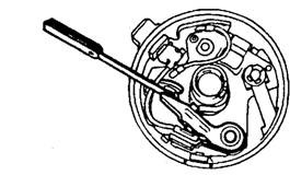 Fig. 16.70. Adjustment of contact breaker gap.
 Fig. 16.71. Dwell.Dwell is expressed either as an angle or as a percentage, which indicates the time that the contacts are closed (Fig. 16.71). A dwell meter is similar to a voltmeter, and when connected between the contact-breaker lead and earth, it shows the average voltage. As the votlage fluctuates when the contacts quickly open and close, the instrument needle is made to indicate a steady reading (Fig. 16.72), which depends on the ratio between the open and closed periods, With the engine in slow-running condition dwell measurement is taken. If incorrect reading is shown the dwell meter can be used while the engine is being cranked and the contacts are being adjusted,
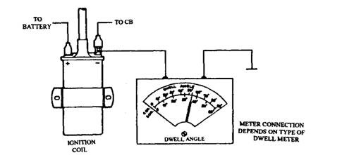 Fig. 16.72. Dwell measurements.Spindle wear and other drive defects can also be identified by observing the change in dwell angle as the engine speed is increased from 1000 to 3000 rpm. Normally the dwell variation should be less than 3 degrees.
Spark Plugs.
Once the plug is used for a long period, erosion inreases the plug gap, and carbon, oil or petrol additive deposits on the internal surfaces decrease the plug’s resistance to misfire. Any shunt path to earth decreases the energy availbale for the spark. Alternation of the spark gap changes the votlage supplied by the coil for a given compression pressure. When gap is too small,low-voltage spark may be insufficient to fully ignite the air-fuel mixture. This effect is felt when cold-starting, slow-running and when the engine is cruising with a weakended misture. If gap is too large, high-voltage spark may demand more voltage than that produced by the coil. Consequently high-speed and cold-starting performances are poor, and erosion of the distributor and spark plug electrodes is severe.For removing the plugs first the HT leads are removed by withdrawing the connectors. Then plug is removed by using a suitable plug socket. Care must be taken to avoid cranking of the ceramic insulator. Inspection of the plug before cleaning often provides inforamtion to the state of tune of the engine. Figure 16.73 indicates the plug appearance for the following conditions.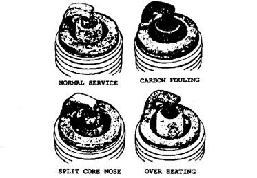 Fig. 16.73. Spark plug condition.
Normal.
The core nose is lightly coated with a gray brown deposit and the electrode is not unduly eroded. Normal erosion wear increases the gap by about 0.016 mm per 1000 km.
Carbon Fouling.
The core nose gives a matt black sooty appearance due to which the HT charge may short to earth without jumping the spark gap. This deposit starts from an over-rich mixture. Also it occurs when the vehicle is engaged on short journeys as well as when the engine operates below its normal running temperature.
Split Core Nose.
Initially a hair line crack appears which soon causes a part of the insulator to break away. This failure is often caused by detonation.
Overheating.
This condition is promoted by any factor that causes overheating of the combustion chamber. Plug temperature increases with ignition advance, so plug failure results due to over-advance.Cleaning of the plug is carried out normally by sand-blasting, followed by air-blasting. A contact file is used to remove deposits on the electrodes at the spark gap and then the gap is reset to the recommended value by bending the earth electrode. A wire-type feeler gauge is more accurate for setting of the gap because a flat feeler blade does not allow for the contour of the earth electrode when it is eroded. Care must be taken to clean all sand from the threads and deposits from the external surface of the insulator. Manual cleaning by a wire brush is an inferiormethod than a sand blast. Using a bruhs may cause damage to the insulate but sufficient pressure is to be applied to remove all deposits.Testing of the plug is carried out in a chamber having the arrangement for the variation of the air pressure while the plug is connected to the source of an HT current at a predetermined maximum voltage. This voltage is sufficient for a new plug to provide good regular sparking up to a given pressure. The plug is screwed into the chamber and left finger tight to allow slight escape of air to improve ionization. The switch is then operated and the air pressure is gradually increased. Sparking is noticed through a window in the chamber and the pressure registered on the gauge is recorded. A good plug should give regular sparking at the electrodes up to the set pressure.When refitting a plug to the engine the correct torque should be applied especially with plugs having a taper seat. In absence of a torque wrench for plug with gasket seat, first tighten finger-tight and then rotate the plug 1/4 turn with a plug spanner. Similarly for taper seat, tighten finger-tight and then use a plug spanner to rotate the plug 1/16 turn.
Ignition Timing.
Static Timing. The need for correct timing is inevitable since incorrect spark timing can cause many problems. When a distributor unit is refitted to an engine the following method may be used for timing (assuming detailed manufacturer’s instructions are not available).(i) Set No. 1 piston to TDC compression.(ii) Connect the drive to have the contacts just opening when the rotor arm is pointing to the distributor segment feeding No. 1 cylinder. The contact position can be determined by using a lamp as shown in Fig. 16.74.(Hi) Connect HT leads to the distributor in the order that the cylinders fire. (iv) Start engine and make final adjustments with timing light.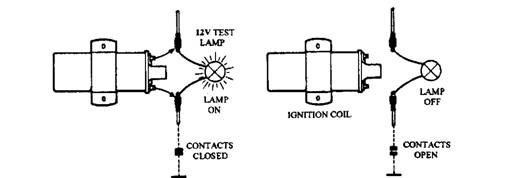 Fig. 16.74. Test lamp method to determine where contact breaker opens.This method is also called static timing an^ manufacturers often provide the crankshaft position at which the spark should occur when the timing is set in this way. A static timing of 4 degrees means “hat when the crankshaft is set to 4 degrees before TDC, the test lamp should indicate that the contact points have just opened.
Stroboscopic Timing.
Strobe-type timing light provides a sudden flash of light precisely when the spark occurs. The high-intensity, short-duration flash is triggered by the HT impulse from No. 1 plug lead. When the lamp is held close to the member that carries the timing marks, the instantaneous flash illuminates the marks and freezes the motion to enable the spark timingto be ascertained (Fig. 16.75). It may be noted that the timing light illumination provides a false impression of the moving parts as stationary and hence care must be taken.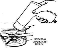 Fig. 16.75. Stroboscopic timing.To set the timing the recommended advance at a certain speed should be known. Set the engine at that speed, and disconnect the vacuum advance pipe. The mark on the crankshaft pulley (or flywheel) should then show the recommended advance if the timing is correct. If the timing is incorrect, the distributor is slackened and the distributor body rotated until the correct setting is obtained. Slight rotation of the distributor body in the same direction as the movement of the rotor arm retards the ignition. When the correct timing is obtained, the distributor is clamped securely, the timing rechecked and finally the vacuum pipe reconnected. The automatic advance mechanism can be tested with this method.After setting the normal timing, the engine speed is raised through set increments. At each speed the timing-light control is varied to make the original timing marks coincide, the angle of advance is observed on the meter. Special timing light are available, which uses a control to provide the flash at a set time after the spark is produced. The extent of this delay is indicated to the operator by an analogue-type meter or digital read out.
Ignition Circuit Testing.
An engine incorporated with conventional ignition system, if fails to start, the following checks can be made :(a) Visual Check. Ensure that the battery is in good condition and check all cable and connector for security.(b) Coil Output. Remove king lead from distributor cap and fit extension (e.g. centre electrode from old spark plug). Hold lead with insulated pliers so that the end of the extension is about 6 mm from a good earth location such as the engine block (Fig. 16.76). Switch-on ignition and crank the engine. If a good spark is observed, but the fault is present in the secondary circuit beyond the coil HT lead, then proceed to Test (g).(c) Contact Breaker. If no spark, or a poor spark from the coil HT lead, examine the contact breaker for the condition of the surfaces and the gap setting. The surface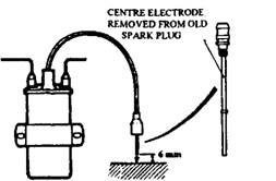 Fig. 16.76. Coil output test.condition is best checked with a voltmeter. Alternatively a 12 V, 3 W test lamp can also be used in parallel with the contacts and the lamp should go out when the contact is closed.(d) Primary Circuit. A high resistance in the primary circuit can be located by measuring the p.d. at various parts of the circuit (Fig. 16.77). The contact breaker is kept closed for the flow of current in the circuit. If the contacts are not set in this position the voltage at three points 1-4 in Fig. 16.77 corresponds to the battery emf unless the circuit is completely broken between points 1 and 4.(c) Capacitor. In absence of the special test equipment, the capacitor condition is found out by substituting a test capacitor. Alternatively, contact breaker can be observed with the engine being cranked and the distributor cap removed so as to assess the degree of arcing. If arcing is severe, the capacitor should be changed.(/) Ignition Coil. A visual inspection of the insulated surfaces should be made for any tracking. Breakdowns of insulation, internal and external, often visible when the coil is loaded. The resistance of each winding can be known by an ohmmeter. , Typical resistances for a conventional coil are 1.2 – 1.4 Q for primary winding and 5-9 kQ for secondary winding.(g) HT Leads. The coil HT lead is reconnected and the HT lead is removed from the spark plug. An extension is added to the end of the lead and the extension is held about 6 mm from a good earth while the engine is cranked. If a sound spark is obtained, then the spark plugs may be faulty. When no spark is observed, the HT circuit between the coil and the spark should be checked.(h) Rotor Arm. The coil king leads are held about 3 mm from the rotor arm blade and the engine is rotated or the contacts are opened manually with an insulated screwdriver. If regular sparking occurs, then the insulation of the rotor arm is faulty.(i) Distributor Cap. The cap is examined visually for any cracks and tracking. The sign of crack is a thin carbon line due to which the HT current takes an easier path than that required. Tracking can cause misfiring, but normally the engine starts with the cap in this condition.Complete breakdown of the king lead does not permit the engine to start whereas a similar failure of a plug causes regular misfiring under load or poor engine performance in general. An ohmmeter should be used to check the resistance of the HT lead, which, in the case of a suppression lead, has a value of 13,000 – 26,000 Q/m.
Diagnostic Equipment – Engine Analysers.
Modern electronic equipment helps for quick and accurate diagnosis of engine faults. These equipment are capable to pin point common and unknown faults in the engine and associated systems, and also to provide the driver with information on the condition of the engine. A number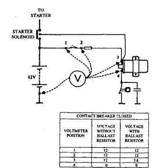 Fig. 16.77. Voltmeter checks on primary circuit.of analysers for this purpose are available, which can be categorised broadly into two main groups:(i) Oscilloscopes for the display of test patterns.(ii) Computers for the test of the engine systems and display the results on a visual display unit (VDU).
Oscilloscope.
A Crypton Diagnostic equipment (Fig. 6.78) comprising of a cathode-ray oscilloscope (CRO) along with analogue and digital meters is used for testing and adjusting the following:• Ignition circuits and components.• Spark timing.• Relative output from cylinders (cylinder balance).• CO emission from exhaust.• Electrical equipment involving the use of basic test meters.
CRO Display.
The pattern formed on the screen is obtained by a spot of light, which sweeps horizontally across the screen in step with the engine speed. Each time a given spark plug fires, the pot is made to return to the left-hand side of the screen. Vertical deflection of the line corresponds with the voltage sensed at a given point in the ignition system. As the phosphorous coating on the inside of the cathode-ray tube retains the image for a short time, the human eye observes a continous line formed on the screen instead of a moving spot of light. Switches are available to select various meter scales and voltage pick-up points in the circuit, which help the operator to analyse the complete process of ignition.In this form the CRO represents a high-speed voltmeter and displays the actual voltage at all stages of the operating cycle, whereas the sluggish movement of an analogue meter needle provides a mean value of the voltage. Before using a CRO for examining ignition patterns, the primary circuit is normally tested with a voltmeter to eliminate the basic circuit faults, which affects the patterns.
Primary Pattern.
The trace in Fig. 16.79 represents an ignition system in good order and indicates the voltage variation in the primary circuit for the production of one spark. At point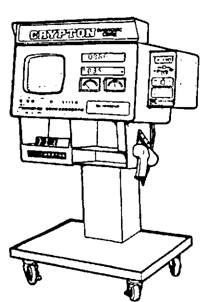 Fig. 16.78. Ignition diagnostic equipment.
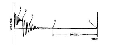 Fig. 16.79. CRO pattern, primary circuit.(1) the contacts open and voltage increases due to self induction. The oscillations at (2) are due to the charge-discharge action of the capacitor. A good capacitor should provide four or five oscillations at this stage.This rise in the voltage at point (3) indicates the end of the sparking period, after which the energy remaining in the primary winding is dissipated as shown in phase (4). Four or five oscillations take place as the energy fades away.The contacts close at point (5) and the trace shows a clean line joining the two horizontal lines. Normally preliminary tests pinpoint a dirty contact condition, but the CRO represents this condition as a hash at the point where the contacts close (Fig. 16.80A).
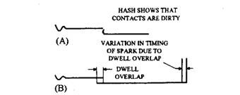 Fig. 16.80. Part of primary pattern, diagram shows two common faults.No large separation in the patterns should be visible when the patterns for each cylinder are superimposed on the original trace. However, if the cam or spindle is worn, the dwell angles vary. This appears as presented in Fig. 16.80B. This is called dwell overlap.For greater accuracy of dwell measurement, modern analysers incorporate a digital meter, which directly indicates the dwell angle. Also these equipments measure the individual dwell given by each cam lobe. After having the values of each dwell angle, th,e smallest angle can be subtracted from the largest angle to find the dwell overlap.
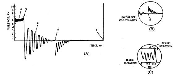 Fig. 16.81. CRO pattern of a secondary circuit.
Secondary Patterns.
A normal pattern shown in Fig. 16.81 represents the voltage variation in the secondary circuit. When the contact is opened at (1) the voltage rises until a spark is produced. Point (2) represents the voltage during the sparking process. Once sparkingstops, the voltage rises (point 3) followed by the dissipation of energy in the secondary widning, which is seen as four or five surges before dying away. At point (5) the closure of the contacts and the start of the current flow in the primary winding mutually induce a small emf into the secondary winding. If the pattern at point (5) is inverted (Fig. 16.8 IB), it indicates incorrect, coil polarity. To correct this LT coil connections are interchanged.Defect in coil windings and poor HT leads provide an unstable pattern and broken trace respectively. Most modern analyzers measure the length of the spark line in milliseconds (Fig. 16.81C). Conventional systems show a spark line of length 0.75- 1.5 ms. Breakerless systems of the inductive discharge type give a 2 ms spark line, whereas capacity discharge systems have a very short line of length 0.15 ms or less.
Parade Order.
Secondary output is represented by each secondary trace, side by side, and the vertical trace lines are broadened (Fig. 16.82) to ease the measurement. Normally the pattern is displayed in the order of the spark plugs firing. This trace provides the voltage initially needed to fire each spark plug. A vertical scale, which can be set at a maximum of either 20 kV or 40 kV measures the voltage applied to each plug and under normal condition the height of each of the prominent verticals is similar. At 1000 rpm the voltage should be 8 – 14 kV, but if the variation exceeds 3 kV, the cause should be determined.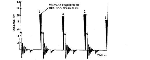 Fig. 16.82. CRO pattern, secondary, parade order.Shorting a plug to earth provides the voltage required to overcome the HT lead resistance and the rotor gap. Normally this voltage should be less than 5 kV. The performance of the spark plugs under load can be assessed by snapping the throttle open and the voltage increases to about 16 kV during this assessment.To measure the maximum voltage output of the coil, the HT lead is removed from the spark plug and is held clear of the engine using an insulated plier. Since most of the coils fitted to vehicles develop a maximum output of at least 28 kV when supplied with a 14 V input, the 40 kV scale is selected during measurement. This test is not recommended on a breakerless system unless a special lead is used to limit the voltage.
Engine Diagnostic Computer.
To meet present demands for accurate testing and efficient fault diagnosis, many engine analysers use a computer. Information on the condition of the engine is displayed on a VDU, which can also be printed. Detachable memory pods {e.g. EPROM) are installed to store data, which include test procedure, printer commands for presenting information on the customer’s report form, and the specifications for the engines to be tested.The computer compares actual information with the specified values of a particular system pin-pointing any faults.The computer also guides the operator through the test program to carryout a health-check of the basic engine systems. Identification of the cause of a fault in a particular system can be found out using the computer. Ignition patterns of the form associated with conventional CROs are not displayed, instead values such as maximum ignition voltages, are shown as a bar chart (Fig. 16.83).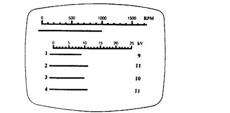 Fig. 16.83. Bar chart display. 16.8.2.
Maintenance of a Breakerless Ignition System
Since several different systems are in use, the manufacturer’s service manual should be referred for the specific information. Appropriate precaution must be taken while checking breakerless systems to avoid an electric shock. In some systems like CD systems a high-voltage charge is still stored even after the ignition is switched-off. The specific tests applied to a breakerless system depend on the type of system. However the basic principles are presented in the following descriptions.
General Maintenance.
Since checks on dwell angle and spark timing are not required, very little routine maintenance is necessary with this system. Also spark plug service intervals are extended. During initial timing of the distributor by the manufacturer, a mark is stamped on the flange to indicate its correct position. If a mechanical advance system is used, timely lubrication of the system should be provided. Timing light may be used to check the operation of the mechanism during servicing.
Ignition Circuit Testing.
If an engine does not start the following two basic checks are carried out before conducting detailed tests on the control module and pulse generator.(a) Visual Check. Ensure that the battery is in good condition, and check all cables and connectors for security.(b) Coil Output. Remove king lead from distributor cap, fit extension to the end of the lead and hold with insulated pliers to keep the end of the extension about 6 mm from the engine block. Switch-on ignition and crank the engine. A good spark indicates that the fault is beyondthe coil HT lead and then the maintenance procedure as for a conventional system is to be followed.It may be noted that damage occurs to the control module if the engine is cranked and the king lead is held at a gap, which is too large for a spark to jump to earth.
Constant-energy Ignition System.
After performing the basic checks the following additional checks are done.(a) Pulse Generator Gap. The gap depends on the type of engine but a typical gap is 0.2-0.4 mm. A plastics feeler gauge blade is used during checking of the gap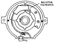 Fig. 16.84. Pulse generator gap.between the reluctor tooth and the pick-up limb (Fig. 16.84).(b) Control Module.Static Check. A voltmeter check at the two points as shown in Fig. 16.85 indicates if the voltage drop across the module is too large or if the module has a poor earth.Cranking Test. The voltmeter is connected between the positive battery terminal and the negative terminal of the coil. If the voltage does not increase when the engine is cranked, then Test (C) should be carried out.
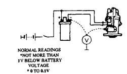 Fig. 16.85. Static test of control module.
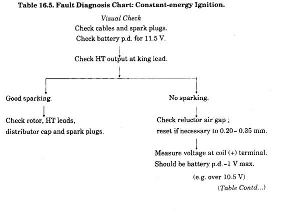
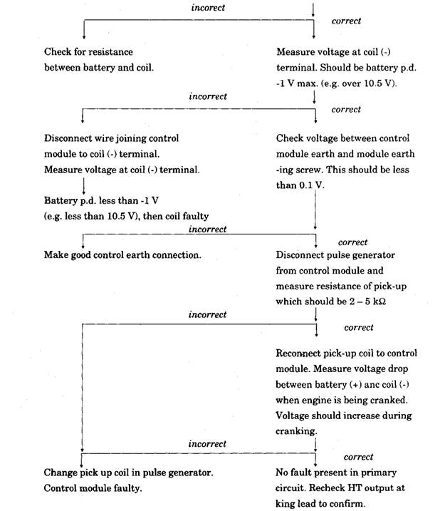 (c) Pulse Generator Coil Resistance (Pick-up Resistance). The pick-up leads from the pulse generator are disconnected at the harness connector and an ohmmeter is used to measure the resistance of the pick-up coil. The resistance value depends on the application (a typicalvalue is 2 – 5 kQ). An integral control module is removed from the distributor to carry out this test. If the reading is incorrect then the pick up may be faulty, but if the resistance value is between the limits recommended, then the control module should be changed.(d) Other Components. The remaining parts of the system are checked in a manner similar to that used for a conventional ignition system. A typical fault diagnosis chart is shown in Table 16.5.
Hall-effect Generator.
Control module and wiring should be checked with a voltmeter similar to the method described earlier. Meter readings at the various points are compared with the specified values, which indicate if the module and generator are serviceable.16.8.3.
Digital System
The multi-plug connector is removed from the ECU. To measure the voltage at the appropriate terminals the voltmeter tests are carried at the cable end of the connector. Voltage checks are also made to the pulse generator and the ignition coil similar to other breakerless systems. The flow of current from an ohmmeter to the Electronic Control Module (ECU) can damage the module, and hence should be avoided. Spark advance given by the ECU is ckecked in the normal manner with a strobe light.
