3.4.
Intake and Exhaust Valves and Mechanisms
3.4.1.
Intake and Exhaust Valves Functions and Arrangements
The valve arrangement in an engine controls the in and out movements of charge and
exhaust gases in the cylinders in relation to the piston positions in their bores. Now-a-days, this
is located in the cylinder head on all the engines. Among the commonly used sleeve, sliding,
rotary, and poppet type valves, the poppet-valve is most common because this offers reasonable
weight, good strength and good heat transfer characteristics.
The most popular shape of the poppet-valve (Fig. 3.32) for automobile application uses a
small cup at one end of the stem. The valve stem is placed in a guide hole made centrally in a
circular passage in the cylinder head. The valve disc head opens and closes the ported passage
leading to the cylinder during in and out movement of the stem.

Fig. 3.32. Valve assembly parts.
Both inlet and exhaust ports are shaped to curve upwards and outwards emerging from one
or both sides of the cylinder head. It is normal to have one inlet and one exhaust valve and port
per cylinder. However, twin inlet and exhaust valve-and-port layouts are also adopted for some
high-performance or large capacity engines. Also, a few engines use twin inlets but only one
exhaust valve.
Valves may be positioned vertically or slightly inclined relative to the cylinder axis,
matching the desired combustion chamber contour. Poppet-valves have different configurations
within the engine relative to the cylinders (Fig. 2.30 and section 2.7). In the overhead-cam engine
(Fig. 3.33A), the camshaft is mounted in the head, either above or to one side of the valve which
improves valve action at higher engine speeds. The valve is operated directly by means of valve
lifters or cam followers, or through rocker arms. In the overhead-valve engine (Fig. 3.33B), the
camshaft is in the engine block, and the valves are operated by valve lifters, pushrods, and
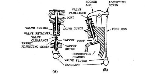
Fig. 3.33. Valves and valve lifters.
A. Valve in L-head engine. B. Overhead valve.
rocker arms. The double-overhead-cam engine has two
camshafts, placed on each side of the valves. One
operates the intake valves and other operates the
exhaust valves.
Intake valves handle cool, low pressure, low den-
sity charges whereas exhaust valves handle hot, high
pressure, high density gases. Therefore, exhaust val-
ves are exposed to more severe operating conditions,
and hence are made from much higher quality
materials than intake valves. The intake valve needs
to be larger than the exhaust valve to handle the same
gas mass (but of low density). From this view point the
size of the exhaust valves is approximately 85% of the
intake valve. Valve head diameter is nearly 115% of
the port diameter and the lift is close to 25% of the
valve diameter. The intake and exhaust valves are

Fig. 3.34. The timing gears.
approximately 45% and 38% respectively of the bore size for
engines with bores from 75mm to 200 mm.
The valve is opened by a cam that is timed to the piston
and crankshaft cycle. It is closed by the use of one or more
springs. The cam is driven by timing gears (Fig. 3.34), chains,
or belts located at the front of the engine. Timing marks on the
timing gears synchronize valve action with piston movement.
3.4.2.
Valve Mechanisms
A. Side Camshaft with Push-rod and Rockers
This type of valve-operating mechanism (Fig. 3.35) uses :
(a) a camshaft, (b) a cam follower (tappet),
(c) a push-rod, (d) a rocker-arm,
(e) a rocker-shaft, if) a return-spring, and
ig) a poppet-valve.
The operating mechanism between the camshaft and the
poppet-valve is known as the valve train.
Advantages.
(a) A comparatively simple short timing chain or simple gear train can be used.
(6) The rocker arm leverage provides a degree of cam-profile lift multiplication which can
be transferred to the valve stem so that a smaller cam lobe can be used.
(c) Adjustment and maintenance is easy and can be carried without diasmantling any
working engine components.
Disadvantages.
(a) During acceleration or operation at high engine
speeds, the push-rod-and-rocker assembly does not
relay the exact cam-profile lift to the valve, because
of the elasticity of the system and the resulting
vibrations.
(b) Larger tappet clearances are required for the expan-
sion and contraction of very long valve-train
mechanism during operation.
(c) Due to the large number of contacting interface
joints, the system develops more wear as well as
more noise.
B. Overhead Camshaft with a Sliding Inverted
Bucket Follower
This type of valve operating mechanism (Fig. 3.36) uses :
(a) a camshaft,
(b) a sliding inverted bucket cam follower
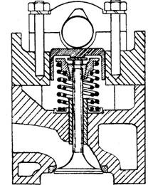
Fig. 3.36. Overhead camshaft with
direct acting inverted-bucket
followers.
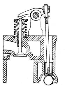
Fig. 3.35. Overhead valve side cam-
shaft with push-rod and rocker-
(c) a return-spring, and
id) a poppet-valve.
Advantages.
(a) This is the most compact and rigid cam-to-valve mechanisms, which directly relay the
designed input cam-profile lift to the valve.
(6) If adequate lubrication is provided, very little wear takes place since the valve stems
are not subjected to side-thrust.
(c) Tappet clearances are generally small and, once adjusted, are maintained for a very
long period.
Disadvantages.
(a) A much more elaborate drive between the
crankshaft and the camshaft is necessary.
(6) Lubrication has to be more accurately controlled
and directed than for other actuating mechanisms.
(c) Adjustment of tappets is relatively more difficult
than in other mechanisms.
C. Overhead Camshaft with Pivoted Rocker-arm
This type of valve operating mechanism (Fig. 3.37) uses
(a) a camshaft,
(6) a pivoted rocker-arm cam follower,
(c) a return-spring, and
{d) a poppet-valve.
Advantages.
(a) The use of the rocker-arm follower provides a
leverage ratio permitting a smaller cam profile in
the system.
(b) The pivot-arm follower has less inertia than that of the sliding-bucket follower.
(c) A single overhead camshaft can operate two separate rows of inlet and exhaust valves.
id) Adjustment of the tappet is normally simple and straight-forward.
Disadvantages.
(a) Motion from the cam to the valve tends to bend the rocker-arm; therefore the system
has to be relatively stiff, and however this characteristic does not match with the
direct-acting bucket-follower arrangement.
(b) Contact between the valve and rocker provides a degree of side-thrust to the valve
stem and guide.
(c) Wear and noise is relatively more than in the sliding bucket follower due to an extra
pivot joint in addition to the other two contact interfaces.
(d) This configuration requires very accurate lubrication.
3.4.3.
The Poppet-valve
The poppet-valve (Fig. 3.38) head is the highest loaded part as it is subjected to uneven
impact stresses across its diameter when the valve comes down on its seat. Also the head has
to withstand thermal streses due to the temperature variation over the head and between the
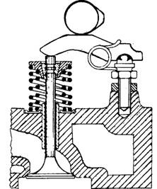
Fig. 3.37. Overhead camshaft with
direct-acting end-pivoted rocker-arm.
head and the stem. The maximum stress con-
centration occurs on the surface of the valve’s
conical seat and in the region where the diameter
changes from the head to the stem. During opera-
tion, the temperature in the centre of the exhaust
valve may be between 1023 and 1123 K and in the
inlet valve between 723 and 823 K. As the
mechanical and thermal stresses are cyclic, if
failure takes place it is of a fatigue nature.
Due to exposure to both dynamic inertia loads
and the products of combustion at these high
working temperatures, the surfaces of the valve
may oxidize and corrode faster. The valve seat
work hardens due to hammering in service, and
any carbon deposit between the seats develops
severe stress concentrations. Any gas leakage be-
tween the seats also develops local overheating which may cause mechanical failure, distortion
or warping, and finally burning of the valve’s conical seat.
To improve the useful service life, the valve should withstand the high operating tempera-
ture, dynamic stresses and the corrosive environment, and have good wear resistance under all
oparating conditions. The shape of the valve should allow the exhaust gases to flow with very
little resistance between the valve and the seat and around the exposed portion of the stem
without absorbing excess heat. Also it should have a section adequate to withstand the stresses
developed due to the repeated impact loads.
The exhaust valve should have
(a) sufficient strength and hardness of resist stretching and rubbing wear of the valve
stem,
(b) adequate hot strength and hardness to resist cupping of the head and rapid seat wear,
(c) good fatigue resistance to combat the repeated cyclic stress loading,
(d) good creep resistance to prevent the head from permanently deforming when operating
at high temperatures and under alternating loads,
(e) good corrosion and oxidation resistance at high operating temperatures and stresses
and in an active corrosive environment,
(/) a moderate coefficient of thermal expansion to limit the thermal stresses due to the
large temperature gradient over the head, and
(g) good thermal conductivity from the valve’s head, so that the heat from combustion can
be dissipated readily.
3.4.4.
Poppet-valve Dimensions
Following are typical valve dimensions (Fig. 3.39) relative to the throat diameter (dt).
Maximum cone diameter, d2 = 105 dt to 1.15 dt
Minimum cone diameter, d\ = 0.95 dt to 1.0 dt
Conical seat width, c = 0.10 dt to 0.12 dt
Parallel thickness of head, hi = 0.025 dt to 0.045 dt
Parallel and taper thickness of head, h% = 0.10 dt to 0.14 dt
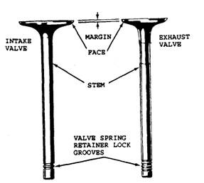
Fig. 3.38. Identification of a poppet valve.
Diameter of valve stem :
For inlet, ds = 0.18 dt to 0.24 dt
For exhaust, ds = 0.22 dt to 0.28 dt
The disc head is initially provided with an angle of
10 to 15 degrees relative to the horizontal followed with
a small radius, r, to match to stem. To improve heat
transfer the stem diameter of the exhaust valve is 10
to 15% greater than that of the inlet valve. For the
maximum flow of fresh charge or exhaust gas between
the valve head and its seat, the annular valve-opening
area must equal the valve or port throat area. To
achieve this the valve lift should be equal to about one
quarter of the valve head diameter. The valve lift, if
less than this value restricts the engine’s volumetric
efficiency, and if much more, increases the inertia of the valve operating mechanism causing
noise and rapid wear.
3.4.5.
Valve Seat and Conical Angles
The valve face angle is chosen for the best possible compromise between valve opening and
valve sealing. Valve opening is maximum at zero face angle, and sealing force on the valve
increases as the angle increases. Poor sealing causes valve burning leading to short useful life.
Generally valve-seat conical angles of 45 degrees or 30 degrees (Fig. 3.40) are used. For a gfven
valve lift, as the angle is decreased the effective flow area around the valve can be increased,
but the pressure on the seat for a given spring stiffness is reduced. To have high seating pressure
arid minimum deposits on the face, a conical valve-seat angle of either 45 degrees or 30 degrees
is recommended for the inlet valve, and only 45 degrees for the exhaust valve because of batter
heat dissipation.
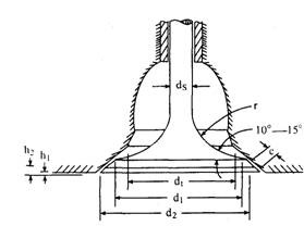
Fig. 3.39. Poppet-valve dimensions.
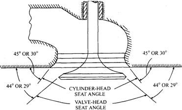
Fig. 3.40. Valve and seat conical face angles.
The valve angle to the plane of the head is normally 0.5 to 1 degree less than the seat angle
in the cylinder head. The difference in cone angles provides a knife-edge contact around the
outer edge of the valve and its seat so that rapid bedding of both the surfaces occurs. This protects
the contact seating faces from combustion and permits the valve head to dish on impact; thereby
load is spread over a larger surface area. If the effective contact seating width is too wide it
reduces the sealing pressure between contact faces and hence its ability to clear the products of
combustion from the faces is also reduced. A too narrow contact faces reduces the heat path
from the valve to its seat when it is closed.
3.4.6.
Valve Operating Conditions
Valve-head Loading.
During operation the valve head and neck are subjected to longitudinal stresses due to the
return-spring load and the valve assembly’s inertia response. Additionally, large thermal hoop
(circumferential) stresses are developed in its head due to the large temperature gradient from
the centre of the head to its rim and from the crown to the parallel portion of the stem. The
strength of the valve material is sufficient to withstand the combination of these two stresses
provided that the contact portion of the seats are not distorted or carbon particles are not trapped
in between. Any unevenness around the circumferential seat interfaces causes severe local
stress concentrations, which may lead to valve failure in a short period.
Valve Head and Neck.
During closure of the exhaust valve its crown is directly exposed to the combustion process.
As the valve opens, the escaping and still burning gases flow around the rim of the head and
underneath, encircling the valve’s neck (Fig. 3.41A). Subsequently they flow through the port
passages to the exhaust system.
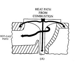
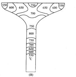
Fig. 3.41. Heat path and temperature distribution for an exhaust valve.
When the valve is closed, most of the heat is transferred to the valve seat and the coolant
circulating in the cylinder head, but when the valve opens, the heat travels only through the
valve stem. Therefore the hottest part of the valve is its neck, the next hottest zone is the centre
region of the crown down to its neck, and the coolest zone is around the valve-head rim and the
parallel region of the stem as it enters its guide (Fig. 3.41B). Thus the valve-head temperature
may be as low as 773 K around the head rim, increasing at the neck under full-load conditions
to around 1073 K and it may rise to 1173 K under abnormal conditions.
Valve Stem and Tip.
The valve stem operates in a guide sleeve and is subjected to a to-and-fro sliding motion
added to a rotary oscillating one in certain cases. The guide sleeve may reach a temperature of
673 K at the mouth of the exhaust port, progressively decreasing to around 473 K at the
valve-spring end. Therefore the stem and guide should have compatible materials to function
effectively for a long time with very little wear under mostly boundary-lubrication conditions.
The valve-stem tip must be sufficiently hard to withstand the tappet impact and in some designs
must resist any scuffing due to relative rubbing between the valve-stem tip and the rocker-arm
pad (Fig. 3.49E). The shaded width in the figure represents the degree of relative movement
between the rocker and the valve-stem tip.
3.4.7.
Poppet-valve Materials
The three basic alloys used in exhaust valves are
(i) Silicon-chromium steels,
(ii) Austenitic chromium-nickel steels,
(Hi) Nimonic nickel-base alloys.
Silicon-chromium steel can function upto temperature of 923 K and early exhaust valves
were made from this steel. A popular composition of this steel is 0.8% carbon, 0.4% manganese,
1.3% nickel, 2% silicon, 20% chromium, and the balance (75.5%) iron.
Addition of the nickel to 12% improves the hot corrosion resistance considerably so that the
valve can operate at slightly higher temperature. Hence valves were made from austenitic
chromium-nickel steels such as ’21-12′, which contains 0.25% carbon, 1.5% manganese, 1%
silicon, 12% nickel, and 21% chromium. A further improved austenitic chromium-nickel steel
is the ’21-4N’ which provides a higher hardness for both cold and hot conditions and a greater
degree of work-hardening. The composition is 0.5% carbon, 0.25% silicon, 9% manganese, 21%
chromium, 4% nickel, 0.4% nitogen, and 64.85% iron. Because of the large amounts of chromium
and manganese the steel absorbs nitrogen, which improves the wear resistance when subjected
to high temperatures and loads.
For high temperature operations and heavy-duty engines nimonic alloys are more suitable
materials. An example is the ’80A’ which has a composition of 0.05% carbon, 1% manganese,
0.6% silicon, 20% chromium, 2% cobalt, 2.5% titanium, 1.2% aluminium, 5% iron and 67.65%
nickel. These nickel-based alloys have a higher hot strength and hardness, and better fatigue
and corrosion resistance than austenitic steels, but are more expensive. To overcome the high
cost of the valve a two-piece valve can be made with a nickel-base-alloy head joined to a steel
stem by friction welding.
The service life of both austenitic steel and nimonic alloy valves can now span upto 150000
km, compared to the traditional 22000 km between relapping of the valve interfaces. For
heavy-duty applications, exhaust-valve head-rim seats may be faced by a hard alloy such as
stellite. This cobalt-based alloy has a composition of 1.8% carbon, 9% tungsten, 29% chromium
and 60.2% cobalt. Since inlet valves operate at temperatures of about 773 K they do not need
such highly alloyed valve material. A typical inlet-valve material is silicon-chromium steel,
which has a composition of 0.4% carbon, 0.5% nickel, 0.5% manganese, 3.5% silicon, 8%
chromium, and 87.1% iron.
3.4.8.
Valve Guides
Normally the valve seat is integrally formed in the head’casting of automotive engines.
Insert seats are also used in some engines, which allow for easy repair of valve seats. Valve seat
distortion is one of the major causes of poor valve service life. Distortion may be transient or
permanent. The former is due to pressure and
thermal stress and the latter as a result of
mechanical stress, so that proper care must be
taken during assembly of the engine.
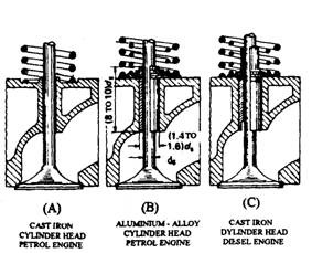
Fig. 3.42. Valve guides.
A. Integral. B. Plain sleeve.
C. Shouldered sleeve.
A guide hole in the cylinder head supports
and guides the sliding action of the valve stem,
so that the head is maintained in a central
position relative to the valve seat while opening
and closing. Such holes are known as valve
guides. For normal duty engines, the guide con-
sists of directly drilled and reamed holes in
case-iron cylinder heads. For aluminium-alloy
cylinder heads and for heavy-duty cast-iron
heads, separate sleeve or bush guides are
pressed into preformed holes (Fig. 3.4).
The guide sleeve or bush is made from good
quality pearlitic cast iron, to minimize stem-to-guide wear, or from bronze to improve the heat
flow to the cylinder-head coolant passages. Although the plain sleeve is adequate for most
applications, but sometimes shouldered bushes are used to position the guide in the cylinder
head. The guide generally protrudes slightly above the spring-seat in the cylinder head, to
prevent excessive oil draining down the stem.
The length of the guiding portion of the sleeve should be 8 to 10 times the stem diameter.
The external diameter of the bush sleeve should be within 1.4 to 1.6 times the stem diameter.
The clearance between the valve stem and the guiding surface of the sleeve varies from 0.02 to
0.05 mm for the inlet valves and from 0.04 to 0.07 mm for the exhaust valves. These values,
however, depend to some extent on the stem and guide materials and the operating tempera-
tures. Worn integral guide holes can be reamed, and the old valves are replaced with new valves
having oversized stems. When existing valve guides are worn, they can be replaced with new
guides.
The valve-to-stem clearance must be sufficient to allow lubrication but excessive clearance
causes the stem to rock and so ‘bell mouth’ the valve guide. As wear occurs, the contact between
the stem and the guide becomes less effective, so that the valve’s mean operating temperature
rises. Lubrication may also deteriorate at this temperature as a result of gum formation.
Protrusion of the valve guides into the exhaust port should generally be avoided otherwise this
may raise the operating temperature of the exhaust valve’s head. Oil leakage past the valve
guide is a problem in the overhead valve engine, especially around the intake valve stem where
vacuum exists. Seals of suitable design made of synthetic rubbers and plastics are, therefore,
used to arrest this leakage.
3.4.9.
Valve-seat Insert Rings
For heavy-duty applications with cast-iron cylinder heads, or for aluminium alloy cylinder
heads, valve inserts are used to withstand the high operating temperatures and the corrosive
atmosphere around the valve seat porting. Also use of insert material with improved impact
strength and hardness resists wear. These inserts (Fig. 3.43) form a rectangular-section ring
having a conical seat on one of the inside edges. The insert must be rigid to withstand the
continuous hammering and be able to dissipate the heat from the poppet-valve head to the
cylinder-head coolant system
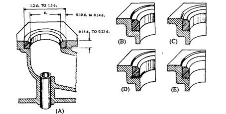
Fig. 3.43. Valve-seat insert rings.
A. Valve-seat insert-ring dimensions. B. Force fit.
C. Rolled-edge fit. D. Sprung-flange fit.
E. Screw fit.
To fulfill these requirements, the radial thickness of the insert wall should be at least 0.10
to 0.14 times the throat diameter. The external diameter of the insert should be within 1.2 to
1.3 times the throat diameter and the height for an insert should be 0.15 to 0.25 times the throat
diameter (Fig. 3.43A). Valve inserts are force fits in recesses machined into the cylinder head.
The interference in cast-iron heads is of the order of 0.0003 times the exhaust valve stem
diameter. Typical interference fits are 0.019 mm per mm of outside diameter for cast-iron
cylinder head, and 0.025 mm per mm of outside diameter for aluminium alloy cylinder head.
While force or shrunk fitting these rings (Fig. 3.43B), they are normally shrunk in liquid
oxygen down to 453 K and then readily pressed into position. In absence of this facility, the
cylinder head is heated in boiling water for half an hour and then the insert is placed as quickly
as possible.
In case of rolled-edge fit the insert ring is forced into its recessed bore, and the edge of the
cylinder-head face is then rolled over to fill up the space provided by the chamfered outer top
edge of the insert (FiD, 3.43C).
For sprung-flange fit, circumferential slots are made on opposite sides at the bottom of the
ring and the lower portion of the insert ring is distorted outwards. When this insert is forced
into its bore, the lower part of the ring springs out into a groove in the recess, which locks the
insert permanently into position (Fig. 3.43D).
For certain aluminium-alloy cylinder head a screw-type joint is used to provide a more
positive grip in the cylinder head (Fig. 3.43E) and to compensate for the large differential
expansion, which usually exists between the insert and its recessed bore.
Seat-insert Materials.
For moderate to high duty cast-iron cylinder head, a low-alloy pearlitic cast iron is used as
insert material. A typical composition of this alloy is 3% carbon, 2% silicon, 0.4% phosphorus,
0.9% molybdenum, 1% chromium, and 92.7% iron. This has a hardness of 270 to 300 Brinell
number.
For moderate to high duty aluminium cylinder head, suitable insert material is a high
nickel-copper austenitic grey cast iron having a high coefficient of expansion as well as good
corrosion resistance. A common composition of this alloy is 2.8% carbon, 2% silicon, 0.45%
phosphorus, 1.8% chromium, 15% nickel, 7% copper, and 70.95% iron. This has a hardness of
160 to 240 Brinell number.
For very-heavy-duty and high-temperature cast-iron cylinder head the insert can be made
from a high-chromium alloy cast-iron containing 1.8% carbon, 1.8% silicon, 0.4% molybdenum,
and 14% chromium. This has a hardness of 270 to 320 Brinell number if heat treated.
3.4.10.
Valve Return Springs
The valve return-spring (or springs) ensures that the valve lift or fall follows precisely the
corresponding cam-profile motion imparted to the follower under both acceleration and decelera-
tion operating conditions.
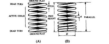
Fig. 3.44. Valve helical-coil springs.
A. Constant-pitch helical spring. B. Variable-pitch helical spring.
Normally helical-coil springs are used (Fig. 3.44A), which work under load in compression.
When the spring is deflected (i.e. compressed during loading) each part of the spring wire is
twisted, and hence is subjected to torsional stress.
The stiffness of a helical spring, which is the ability of the spring to resist deflection under
the application of a load, is proportional to the fourth power of the spring wire diameter and is
inversely proportional both to the cube of the mean spring coil diameter and to the number of
active coils, all other conditions being equal.
Therefore, x a (d4/D3N)
where x is spring deflection,
d is spring-wire diameter,
D is spring coil diameter,
and N is number of active coils.
If wire diameter is doubled the spring strength is increased sixteen fold, if the coil diameter
is halved its strength is increased eightfold, and if the number of active coils is halved its
strength is increased only twofold.
The coils of a spring that deflect when a load is applied are called the active coils. End
terns or part turns on a compression spring, which do not deflect are known as dead coils. The
dead coils at both ends of the spring are ground flat perpendicular to the spring axis, and the
two ends are arranged diametrically opposed. This prevents the spring length bowing under
compression so that the fatigue life of the spring is considerably reduced. The spacing distance
between adjacent active coils is known as the pitch of the spring.
The valve spring in the normal position maintains the valve closed on its seat and provides
sufficient valve-train inertia forces so that the valve movement closely follows the cam profile
motion at all speeds. For the spring not to be overloaded, there should be at least 4.5 active coils.
Too many coils, however, reduce the spring stiffness causing more likely the spring surge. The
valve and spring should open slightly beyond the normal fully open position so that the coils are
prevented from crashing together when over speeding causes valve bounce.
Relaxation of the spring occurs as it plastically deflects at average temperature of about 423
K or even more under cyclic conditions of stress. In this condition it does not recover its original
free length when the external load is released. Therefore over a period of time, the force exerted
by the spring is reduced.
Valve Spring Surge.
Resonance occurs when the natural frequency of vibration of the spring or its multiples
synchronizes with disturbing vibrations produced by the action of the cam against its follower.
During resonance, the coils at the stationary end of the spring completely or almost completely
close together in the initial stages of valve lift, because of their inertia, and successive coils away
from this end close up to a lesser extent. The coils furthest from the cam follower close up most
during the final stages of valve opening. A collapse of spring resistance takes place due to which
some of the coils temporarily lose their pitch and move closer together sweeping or surging from
one end of the spring to the other. When this spring surging occurs, the natural closing action
of the coil spring becomes out of control and the valve movement, therefore, no longer follows
the camprofile rise, dwell, and fall.
Variable-pitch Springs.
To reduce spring surge, a variable-pitch spring is incorporated in which the pitch between
adjacent coils from the valve-stem tip to the stationary valve guide and seat is progressively
made smaller. As the valve opens, the coils are progressively compressed solid, starting from
the close-pitch cylinder-head end, due to which the number of active coils is reduced. Conversely,
during closing of the valve, the number of active coils increases. This variation of number of
active coils during opening and closing of the valve provides a variable spring rate and a
constantly changing natural frequency, which reduces both springs resonance and surge.
Double springs.
The double nests of springs in the system provides high spring loads on the valve for a given
valve-spring space. To exert the same total force, the stiffness of each spring in the nest has to
be lower than that of a single spring. Therefore, the natural frequencies of the nested springs
is also be lower (since a spring’s natural frequency is proportional to the square root of its
stiffness), which encourages surge.
One advantage of using double springs is that, under favorable conditions, resonance in one
spring may be partially damped out by the no resonant action of the other. Moreover, if any one
spring breaks, the other continues to operate. This avoids valve drop into the cylinder causing
damage.
Pre-stressing.
Springs are normally pre-stressed by scragging, in which the spring is compressed until the
stress in the outside fibers of the wire is greater than the yield stress of the material, causing
plastic deformation of the outside steel fibers. This induces residual stresses so that the yield
strength of the steel is raised.
Shot-peening.
Springs are provided with a short-peening treatment, which considerably improves the
fatigue strength of the steel. During treatment, the spring is bombarded all over with round
particles of hardened steel (shot) at high velocity. This produces compressive stresses in the
outside fibers of the coil wire. These residual compressive stresses help to prevent tensile
stresses being developed on the surface of the wire. But, if any imperfection exists in the outside
fibers of the wire, such tensile stresses initiate crack propagation leading to fatigue failure.
Valve Spring Materials.
Either a plain high-carbon steel or a low-alloy chromium-
vanadium steel is used to manufacture valve springs. The high-carb-
on steel contains 0.4 to 0.8% carbon, 0.3% silicon, and 1.0% man-
ganese. The chromium-vanadium steel contains 0.4 to 0.5% carbons,
0.2% silicon, 0.6% manganese, 1.0 to 1.5% chromium, and a minimum
of 0.15% vanadium. The steel wire is supplied in the softened state.
It is ground all over to a good surface finish, followed by cold drawing
to impart the necessary high tensile properties. The wire is coiled into
the spring shape and is then given a blueing, a stress-relieving
treatment.
3.4.11.
Valve Spring Retention (Locks)
The return-spring (or springs) keeps the valve in the closed
position until actuated by the camshaft. It acts against a spring-
retaining plate fixed to the end of the valve stem (Fig. 3.45). This
retaining plate contains a central tapered hole which, when in posi-
tion, fits over a shallow circular groove machined near the end of the
stem. Two tapered half collects are wedged in between the spring-
plate’s conical wall and the grooved portion of the stem. The internal
protruding circular notches or ribs formed on the collects lock them
to the stem groove. The continuous pulling of the spring-plate by the
spring maintains the collects’ grip on both the stem and the spring-plate. The underside of the
spring-plate is normally stepped to position either one or two springs.
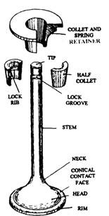
Fig. 3.45. Poppet-valve
spring retention.
Valve-rotators.
Valve-rotators may be non-positive or positive types. The former type has a non-positive
action which enables the valve to ratate at random when it is opening and closing. The latter
type has a positive action which directly rotates the valve as it operates. The objective of valve
rotation is to improve valve seating by clearing the seat faces of carbon particles, which might
otherwise become attached to them. The gradual reposition of valve relative to its seat improves
valve and seat life.
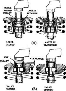
Fig. 3.46. Non-positive valve rotators.
A. Split-collect valve-rotator.
B. Thimble valve rotator.
Non-positive Valve-rotators.
Out of the two
common designs used in non-positive arrangement
one method incorporates loose-fitting collets, while
the other adopts a thimble which fits over the valve-
stem tip.
ii) Split-collets Valve-rotator.
The specially
designed collects in this approach (Fig. 3.46A) permit
the valves to rotate under certain conditions. The
stem of the valve has three annular grooves of semi-
circular section and the inner surface of each collet
has three semicircular ribs. These press against each
other providing a small radial clearance between the
valve and the collects. The vibration of the valve gear
rotates the valve at between 15 and 25 rpm at engine
speeds above 1500 rpm.
Low-carbon-steel stip is used to make the collects.
The strip is extruded to the required section. A length
is cropeed and pressed to the final curvature. The
collects are finally case-hardened.
(ii) Thimble Valve-rotator.
In the thimble rotator
design (Fig. 3.46 B), a steel cap fits over the end of the
valve stem and rests on two semicircular collets which fit
in the valve-stem groove below.
The valve spring maintains a pressure on the retainer
against these collets and so keeps the valve closed. When
the valve is required to be opened, the rocker-arm presses
down the cap which in turn bears against the two collets,
and then moves the valve spring and retainer downwards.
The spring pressure is now taken by the cap, and hence
the valve is freed from spring pressure. It is still moved
downwards, because the closed end of the cap then abuts
the valve-stem end, but it is free to turn.
(Hi) Positive Valve-rotation (Rotocap).
This arrangement (Fig. 3.47) incorporates a ball-retaining plate
with six ramped grooves (only four are shown in the figure)
for balls to roll along. A small spring pushes each of these
balls to one side. A Belleville-type dished spring washer
fits over these balls to form an upper race, which is
supported on its outer edge by a spring-seat retainer. This retainer holds the whole assembly
together and also provides a seat for the helical-coil valve springs.
In the closed position of the valve, the dished washer is suspended between the spring-seat
retainer and the ball-retainer, so that the balls move freely to the top of the ramp and abut
against the end of the groove. During opening of the valve, the dished spring washer deflects
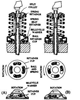
Fig. 3.47. Positive valve rotator.
A. Valve closed. B. Valve open.
with the increase in the compression load on the valve spring. The outer edge of the dished
washer bears against the spring-seat retainer as before, but the inner part of the washer now
bears against the six balls and hence pushes them down their ramps. The ramps are so shaped
that, as contact with the washer is maintained, the spring-seat retainer is rotated and hence
the poppet-valve is rotated by the same amount.
As the valve closes, the washer comes back to its original position between the spring-seat
retainer and the ball-retainer. This releases the load on the balls due to which the small bias
springs now push the balls up their ramps and thereby bring the spring-seat retainer and the
valve assembly back to its starting position.
3.4.12.
Rocker-shaft
Rocker-shaft provides a rigid pivot sup-
port for the rocker-arms. These shafts are
machined from hollow steel tubing. These
are mounted and clamped on cast-iron or
aluminium-alloy pedestals, which are
generally fitted between each pair of rock-
er-arms (Fig. 3.48). Therefore, a four-
cylinder engine has four pedestal support
brackets.
For lubrication purposes radial holes are drilled through the rocker-shaft to align with each
rocker-arm, and both ends of the shaft are plugged to prevent the oil leakage. One of the support
pedestals normally incorporate a vertical drilled hole to supply the oil from the camshaft to the
hollow rocker-shaft. This hole matches with a corresponding radial hole in the shaft. When
reassembling the rockers and shaft, these two holes must align, to restore oil supply to the shaft.
The material for these tubular shafts is carbon steel, a typical composition of which is 0.55%
carbon, 0.2% silicon, 0.65% manganese, and the balance iron. After machining, the shaft is
case-hardened to withstand the rubbing action.
3.4.13.
Rocker-arm
A rocker-arm rocks or oscillates about its pivot (Fig. 3.49) and relays the push-rod up-and-
down movement to the stem of the poppet-valve. Therefore this arm acts as a rocking beam.
The pivot (either a shaft or a spherical fulcrum post) is offset and positioned in the push-rod
so that for a given cam lobe rise, the corresponding valve life is about 1.4 times greater. This
allows lobe profile of 40% smaller than is otherwise necessary. The actual rocker-arm pivot ratio
and therefore the cam lobe size vary to certain extent depending on design requirements.
Rocker-arms may be manufactured from materials which can be cast, forged, or cold-pressed
to shape. These are cast from malleable cast iron with induction-hardening at selected regions.
For forging a medium-carbon steel with a typical composition of 0.55% carbon, 0.2% silicon,
0.65% manganese, and the balance (98.6%) iron can be used. This can be hardened by quenching
from a temperature of 1085 K to 1115 K and then tempering at a suitable temperature between
825 K and 975 K. For cold-pressing a low-carbon steel of composition 0.2% carbon, 0.8%
manganese, and the balance (99%) iron can be used. Rockers, when manufactured in this
method, incorporate a hardened-steel contact pad attached at the valve-stem end.
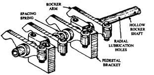
Fig. 3.48. Rocker-shaft assembly.
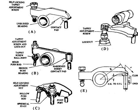
Fig. 3.49. Valve rocker-arms.
A. Forged or cast rocker-arm with central pivot and end adjustment.
B. Pressed-steel-sheet rocker-arm with central pivot and end adjustment.
C. Cast or pressed-sheet rocker-arm with central pivot and adjustment.
D. Forged or cast rocker-arm with end pivot and adjustment.
E. Geometrically best rocker-to-valve-stem layout.
3.4.14.
Push-rod
The push-rod is a strut which transmits the to-and-fro cam-follower movement to one end
of the pivoting rocker-arm. Both ends of the push-rod constitute part of pair of semi-spherical
ball-and-socket joint, which permits the rod to tilt slightly and revolve when the rocker-arm
oscillates about its pivots. The bottom of the rod is convex that fits in a matching recess in the
follower. The top of the rod is expanded to support a concave-recess seat that locates with the
adjustable tappet screw on the end of the rocker-arm. For medium capacity engines the push-rod
in general is solid (Fig. 3.49B), but for large engines hollow rods with hardened end-pieces forced
into the tubing are used (Fig. 3.49C).
Push-rods are usually manufactured from carbon-manganese steel, a popular composition
of which is 0.35% carbon, 0.2% silicon, 1.5% manganese, and the balance (97.95%) iron. The rod
is hardened by quenching it from a temperature of 1113 to 1143 K and then tempering between
823 and 933 K. This produces a hardness of 220 to 280 Brinell number. Alternatively a steel
with a higher carbon content suitable for induction-hardening is used.
3.4.15.
Cam Follower (Tappet) and Lifter
The cam follower (Fig. 3.50) through its eccentic lobe converts the angular movement of the
camshaft into a reciprocating movement. This movement is directly proportional to the amount
the lobe profile that is deviated from the base circle. Two common forms of sliding followers are
the mushroom follower and the bucket or barrel follower.
The mushroom follower uses a relatively small diameter solid cylindrical guide stem. The
stem has a large disc- or mushroom-shaped head formed at one end to contact the cam profile.
Its other end is of concave shape recessed to form a semi-ball-and-socket joint with the bottom
of the convex push-rod end.
The bucket or barrel follower is a hollow cylindrical sleeve with an enclosed bottom. Its
top side is concave recessed to position the push-rod semi-spherical end. The underside of the
sleeve is flat to transfer the cam-lobe profile rise to the follower. Sometimes helical slots are
formed on the cylindrical walls to reduce weight as well as improve lubrication.
The mushroom-type follower can incorporate a shorter push-rod, which improves the
rigidity. The bucket follower, however, provides side-thrust support. The centre line of stroke
in the follower is slightly offset from the mid width of the cam (Fig. 3.50C) to distribute wear
over its bottom face. Therefore, during operation, the follower tends to revolve every time the
lobe rubs against it.
To have a very slight curvature, the face of the follower is provided with a spherical radius
of about 1 m (Fig. 3.50A). To match the centre of the follower face, which stands out about 0.08
mm, with this curvature, the cam lobes are ground with a taper of the order of 3 to 4 degrees
(Fig. 3.50B). This combination helps to reduce tappet and cam wear. In L-head engines the valve
clearance is adjusted by the use of a tappet-adjusting screw and in I-head engines by rocker arm
adjusting screws.
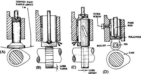
Fig. 3.50. Cam followers (tappet).
A. Mushroom follower. B. Bucket or barrel follower.
C. Enclosed bucket follower with helical slots. D. Roller follower.
Roller followers are used for some heavy-duty applications. However these followers must
be prevented from rotating for which a slot guide-screw is always provided (Fig. 3.50D).
The latest model engines have hydraulic tappets (lifters), which are very quiet and have no
valve clearance. The major parts of a hydraulic tappets consist of a hollow cylinder body
enclosing a closely fit hollow plunger, a check valve, and a push-rod cup. Engine oil pressure is
fed by an engine passage to the exterior tappet body. An undercut portion allows the oil under
pressure to surround the tappet body. Holes in the undercut allow the oil under pressure to go
into the centre of the plunger. Then it flows down, through the check valve, to a clearance space
between the bottom of the plunger and interior bottom of the tappet body base, and fills this
space with oil at engine pressure. The operating principle of the hydraulic tappet is illustrated
in Fig. 3.51.
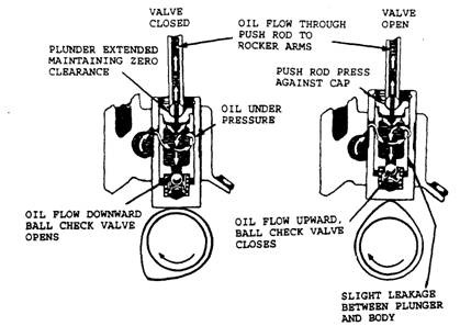
Fig. 3.51. Hydraulic tappet (lifter) operation.
The pushrod fits into a cup in the top open end of the tappet plunger. A hole in the push-rod
cup, push-rod end, and hollow pushrod allows oil to transfer from the tappet piston centre, up
through the pushrod to the rocker arm, where it lubricates the rocker arm assembly. As the cam
starts to push the tappet against the valve train, the oil below the tappet plunger is squeezed
and it tries to return to the tappet plunger centre. However, a tappet check valve traps the oil
below the tappet plunger, hydraulically locking the operating length. The tappet then opens the
valve as one solid unit. When the tappet returns to the flat of the cam, engine oil pressure again
replaces any oil if leaked out.
Similar to the camshaft the follower is manufactured from a chilled low-alloy cast iron
containing iron, carbon, silicon, manganese, and chromium.
3.4.16.
Tappet Clearance Adjustment for Push-rod Mechanisms
Tappet clearance is provided to accommodate expansion and contraction of the valve and
its operating mechanism. Depending on the method of tappet adjustment two basic types of
rocker-arm arrangement in use are
(i) Push-rod-end adjustment, and (ii) Central-pivot adjustment.
Push-rod-end Adjustment.
The rockers are centrally pivoted on a rocker-shaft (Fig. 3.49A and B). The arm has a
hardened face pad with a curved surface at one end for smooth contact with the valve-stem tip.
A thraded hole at the other end holds an adjustable tappet screw with a lock-nut. The tip of this
screw has a hardened spherical ball. This ball fits into a matching concave recess formed in the
top of the push-rod.
For adjustment the correct size of feller gauge is slipped between the valve-stem tip and the
rocker pad. Then the lock-nut is slightly slackened and, using a screwdriver, the tappet screw
is turned to either increase or decrease the clearance. For correct clearance, the feeler blade
should just feel grip as it is pulled across the valve-stem tip. The lock-nut is then tightened and
the clearance rechecked. Self-locking screws are also sometimes used (Fig. 3.49A).
Central-pivot Adjustment.
This mechanism (Fig. 3.49C) incorporates the hollow malleable-iron or pressed-steel type
of rocker having a curved valve-tip contact face at one end. At the other end, a hardened spherical
recess receives the ball-ended push-rod. The rocker pivots on a spherically faced fulcrum seat
of case-hardened sintered-iron. A self-locking nut on a stud post, fixed into the cylinder head,
holds the rocker. The push-rods are located and positioned by guide fork-plates fixed on the
cylinder head.
For the tappet clearance adjustment, the feeler blade is pushed between the valve-stem tip
and the rocker face. The central self-locking nut is then turned either way until the correct
clearance is obtained by the feeling of grip that the valve -stem tip and rocker impart to the
feeler blade.
Camshaft Positioning for Push-rod Tappet Adjustment.
Before measuring the tappet clearance, it is necessary to rotate the camshaft until the
follower is on the base of the cam and furthest from the cam-lobe nose. One of the three different
methods of positioning the camshaft is as follows.
The crankshaft is rotated until the valve being adjusted is fully open. It is then turned
further through one complete revolution to bring the follower on to the base of the cam. The
camshaft moves at half crankshaft speed. Therefore to move the cam-lobe nose from its top
position to the bottom, i.e. 180 degrees camshaft movement, a corresponding crankshaft
movement of 360 degrees is required.
3.4.17.
Valve Cooling
It is necessary to cool the exhaust valve directly or indirectly as it becomes very hot due to
the passage of hot exhaust gases. The valve face and stem conduct heat to the surrounding and
they are relatively cooler than the valve head. A poor valve may cause a valve to run hotter
reducing its life considerably. Additional water circulation is usually provided near the exhaust
valve seating in the engine head. Sodium cooled valves are used in the heavy duty engine and
aircraft engines. These valves have a hollow head and stem, which is partly filled with sodium
or a mixture of salts. During operation of the valve the up and down movement of sodium
transfers the heat near the head portion at a faster rate.
3.4.18.
Timing the Valve of an Engine
During the assembling of an engine the drive between the crankshaft and the camshaft
must be connected properly so that the valves open and close at the correct times in relation to
the movement of the crankshaft and the piston. This operation is known as timing the valves,
which is carried out through three main stages as follows. For the engine with more than one
camshaft, each one has to be timed individually.
(a) Set the crankshaft in the position in which one of the valves should open or close. (It
is usual to work on the opening point of the inlet valve, but any other point can be
used.)
(b) Set the camshaft in the position in which it is about to open the inlet valve (or whatever
point is chosen).
(c) Connect up the drive to the camshaft.
Suitable parts of the engine are usually marked, to assist in timing the valves (Fig. 3.34).
The timing gear or sprocket is keyed to the crankshaft and can be fitted in one position only.
The camshaft gear or sprocket is similarly fixed to the camshaft in such a way that it can be
attached in one position only. By lining up marked teeth on these gears, the crankshaft and
camshaft are placed in the correct positions for connecting up the camshaft drive. These gears
are hidden inside the timing cover when assembled. To enable the timing to be checked without
removing the cover, the pulley is usually marked in a position corresponding to TDC in one of
the cylinders. If the pulley is not marked in this way, the TDC position can be found by any one
of several methods, of which the following is an example.
On most modern engines the piston can be felt by inserting a rod through a sparking-plug
hole. Turn the engine until the piston is approximately 10 mm below its highest position, and
file a notch on the rod exactly opposite the top of the plug hole when the end of the rod is resting
on the piston. Mark the crankshaft pulley opposite some suitable fixed reference point. Now
turn the engine crankshaft so that the piston passes TDC and begins to move down the cylinder.
Stop when mark on the rod reaches the top of the plug hole, and put a second mark on the pulley
opposite the fixed reference mark. Mark the mid-point of the distance between the two marks
on the pulley. The piston is at TDC when this last mark is opposite to the fixed reference point.
Valve timing marks can also be made on the flywheel. If the circumference of the flywheel
is divided by 360, a figure is obtained, which represents the distance measured round the
flywheel rim equivalent to one degree. For example if the circumference of the flywheel is 800
mm and the inlet valve opening point is 9 degrees before TDC, the distance to be measured
round the flywheel rim is (800 x 9/360 = ) 20 mm.
There are several ways, by which the opening point of the valve can be found. First of all the
valve clearance must be correct, since variation of clearance causes a considerable variation in
timing. (Some manufacturers stipulate a different clearance for valve timing from that used for
running). If the valves are push-rod operated and the end of the push rod is accessible, it can
be spun easily between finger and thumb while the valve is on its seat, but becomes stiff to turn
as the valve is on its seat, and becomes stiff to turn as soon as the valve begins to open. An
alternate method is that in which, a feeler gauge is inserted in the clearance between the rocker
(or tappet) and the valve stem is nipped at the moment the valve begins to open. In this case
the valve clearance must be increased by an amount equal to the thickness of the feeler used.
