20.2.
Engine Disassembly
The transmission and clutch are removed. The procedure for removing a standard transmission and clutch is described in chapter 25 and 24 respectively. The procedure for removing an automatic transmission is given in chapter 25. All remaining accessories are removed from the engine and stored in a safe place. Engine disassembly is preferred to be done on an engine stand; however it can also be carried out on blocks on a clean floor. The manifolds and heads are removed as described in section 20.2.1.

Fig. 20.2. Normal carbon deposits on the pistons.
Visible condition of the combustion chambers and lifter chamber, and any head gasket leakage, can be noticed with the heads off (Fig. 20.2). These conditions should be noted. At this stage, the cylinder taper and out-of-round should be checked just below the ridge and just above the piston when it is at the BDC as shown in Figs. 20.3 and 20.4. These measurements indicate the extent of work necessary on the cylinder wall. If the cylinders are worn beyond limits, they require re-boring to bring them back to a satisfactory condition with recommended tolerances.

Fig. 20.3. Location of the cylinder bore wear.

Fig. 20.4. Measuring the cylinder bore wear immediately after the head is removed.
The engine is turned upside down and the oil pan is removed. This is the first approtunity to notice the working parts in the bottom end of the engine. Visual observations of the deposits again provide an indication of the engine condition. Heavy sludge indicates infrequent oil changes. Hard carbon indicates overheating. The oil pump pick-up screen should be checked to find out how much plugging exists. The connecting rods, caps, and main bearing caps should be inspected to make sure they are numbered. If not, they should be numbered using number stamps or prick punch. The marking of parts help to reassemble them in exactly the same position. The identification punch marks should be made on the mating line (Fig. 20.5).
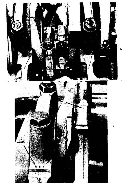
Fig. 20.5. Rod and bearing caps identified to show their position. A. Numbers. B. Punch marks.
20.2.1.
Head Removal
The normal procedure for carrying out only upper-engine service is to leave the engine in the chassis, and remove the components required to undergo the servicing. It is advisable to clean the engine exterior and the engine compartmen. before taking up any job. A clean engine is easier to work on, it helps keep dirt out of the engine, and it minimizes accidental damage from slipping tools.
Working on top of the engine becomes easy if the hood is removed. With fender covers in place, the hood is loosened from the hinges by removing two or three cap screws on each side. With a person on each side of the hood to support it, the hood is lifted off as the cap screws are removed. The hood is usually stored on fender covers placed on the top of the automobile, where it is most secured.
The coolant is drained from the radiator arid engine block to avoid entering of the coolant into the cylinders during removal of the head. The exhaust is disconnected from the exhaust pipe and muffler. On some engines, the exhaust pipe can be removed easily from the manifold. On others, it is easier to separate the manifold from the head and leave it attached to the exhaust pipe. On V-type engines, the intake manifold must be removed before the heads can be taken off. In most cases, a number of wires, accessories, hoses, and tubing must be removed before the manifold and head can be removed. If the engine is not familiar, it is a good practice to put tape on each of these items removed (Fig. 20.6). The tape can be marked to indicate the location so that each items can be easily reassembled.
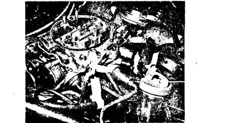
Fig. 20.6. Connecting hoses and wires marked before removing them from engine.
The following disassembly procedure applies primarily to push rod engines. The procedure has to be modified to certain extent to working on overhead cam engines.
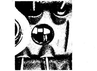
Fig. 20.7. Camshaft visible after the intake manifold is removed.
Removal of the rocker covers provides the first opportunity to see inside a portion of the engine. A good visual examination of this area should be made to identify and find out the cause of abnormal condition, if any. Special attention should be given to the type and quantity of deposits. The rocker arms, valve springs, and valve tips are examined for any defects.
The manifold hold-down cap screws and nuts are removed. In case the gaskets are stuck, a flat blade, such as a putty knife, can be used to loosen them. Care must be taken to avoid damaging the parting surface as the gasket is loosened. When the manifold and lifter valley cover are off on V-type engines, another opportunity is available to examine the interior of the engine. Here again, it is advisable to check the deposits. The push rods and lifters are exposed for a visual inspection. On some V-type engines, it is possible to observe the condition of the cam at the bottom of the lifter valley (Fig. 20.7).
It is good practice to keep all of the engine parts in order so that their exact location in the engine is known. It provides an opportunity to find out abnormal conditions to their sources. Additionally it also allows putting operating parts back together in the same way they were operating before service.
There are two views regarding cleaning an engine while servicing only a part of the engine. As per one view, the deposits should not be disturbed on any part of the engine not directly involved in the repair. This is supported with reason that it is difficult to remove loosened deposits, and it consumes additional time. The other view recommends thorough cleaning of all accessible deposits so that the engine can serve better as long as possible after the repair. This, however, increases the cost of repair to the customer.
With the manifold off the V-type engine, any observable abnormal conditions are noticed, then the rocker arms are loosened and the push rods removed. When reconditioning the valves, it is usual practice to leave the lifters in place. They can be removed at this stage, only if they are causing the problem or if the entire valve train is required to be serviced.
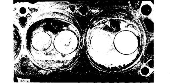
Fig. 20.8. Normal combustion chamber deposits.
The final major disassembly is the removal of the head. The head cap screws are removed and the head is lifted from the block deck. If the head gaskets are stuck, careful prying on the
head loosens the gasket. Special precautions should be taken to pry on edges of the head without causing any damage. Parting surfaces should not be scratched. Scratched or burred surfaces lead to leaks on the repaired engine.
The combustion chamber is exposed when the head is removed. The combustion chamber pocket in the head and the top of the piston should be inspected thoroughly. The most common condition is the deposits as shown in Fig. 20.8. A normal combustion chamber is coated with a layer of hard, light-coloured deposits. On the other hand thick, dirty, black deposits indicate that it has been running too cold. Heavy wet deposits result from oil that is entering the combustion chamber. If oil consumption is excessive, the large quantity of oil entering into the combustion chamber washes the carbon deposit from the entry location.
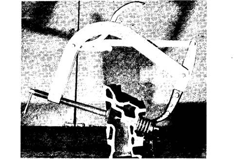
Fig. 20.9. Valve spring is compressed to remove the valve locks.
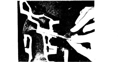
Fig. 20.10. Removing burrs at the valve lock grooves before removing the valve from the guide.
With the heads removed and placed on the bench, the valves are removed. A C-type valve spring compressor (Fig. 20.9) is normally used to free the valve locks or keepers. The valve spring compressor is air-powered in production shops where valve jobs are being done regularly. Mechanical valve spring compressors are used where valve work is occasionally done. After the valve lock is removed, the compressor is released to free the valve retainer and spring. These are lifted from the head along with any spacers being used under the valve spring. At this stage also the parts should be arranged in order to aid in diagnosing the exact cause of any malfunction that shows up. The valve tip edge and lock area should be lightly filed or stoned (Fig. 20.10) to remove any burrs before sliding the valve from the head. Burrs scratch the valve guide.
When all valves are removed, the valves, springs, retainers, locks, guides and seats should be examined visually and any obvious faults should be noted. Parts those are found not repairable should be marked and set aside for later reference and fault diagnosis.
20.2.2.
Piston and Connecting Rod Removal
The ridge above the top ring travel must be removed before the piston and connecting rod assembly is removed. This avoids catching a ring on the ridge and breaking the piston. Failure to remove the ridge probably results in breaking the second piston land when the engine is run after reassembly with new rings (Fig. 20.11). The ridge is removed with a cutting tool that is fed into the metal ridge. A guide on the tool prevents accidental cutting below the ridge. The ridge reaming job should be done carefully with frequent checks of the work so that only necessary material is removed. One type of ridge reamer is shown in Fig. 20.12.
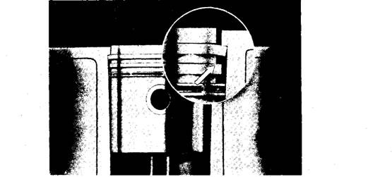
Fig. 20.11. Usual failure of the second land if the cylinder edge is not removed before removing the pistons.
For the rod to be dismantled, the connecting rod nuts are taken off to remove the rod cap with its bearing half. The rod bolts are covered with protectors made of aluminium or short pieces of rubber hose (Fig. 20.13), so that the rod bolts are kept from touching the bearing journal surfaces on the crankshaft. If they touch, the sharp threads of the bolts easily nick the surface as illustrated in Fig. 20.14, thereby damaging a new bearing, The connecting rod is carefully pushed up until the piston rings are free of the block deck, because the piston ring drag stops when the rings are free of the cylinder bore. Excessive force on the rod causes the piston to jump
out of the bore when the ring moves out past the block deck. If the piston is not held, it falls to the floor and is damaged. Care should also be taken to avoid hitting the bottom edge of the cylinder as illustrated in Fig. 20.15. A burr here scratches the piston skirt. When removed, the rod cap and bearing should be placed back on the rod to keep them together. This procedure of dismantling should be repeated with all the other pistons. No further parts need to be removed from the block when only the ring-and-valve-job is to be carried out.
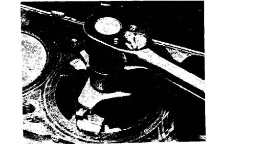
Fig. 20.12. Ridge removal.
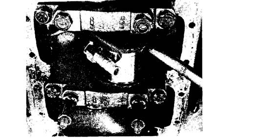
Fig. 20.13. Crankshaft protectors on rod bolts.
20.2.3.
Shaft Removal
The engine must be removed out of the chassis if the crankshaft is to be dismantled. The camshaft can be removed with the engine in the chassis on most automobiles, but it is necessary to remove the radiator and grill.
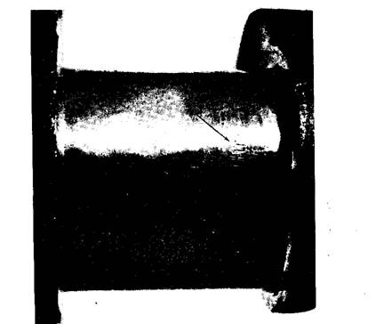
Fig. 20.14. Crankshaft journal nicked by a rod bolt.
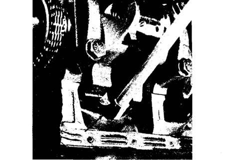
Fig. 20.15. Connecting rod hitting the cylinder skirt bottom due to careless removal.
The next step in disassembly job is to remove the water pump and crankshaft damper. The damper should be removed only using a threaded puller (Fig. 20.16). If a hook-type puller is used around the edge of the damper, it may pull the damper ring from the hub. If this happens, a new damper assembly has to be installed. With the damper off, the timing cover can be removed, which exposes the timing gear or timing chain. These parts are examined for excessive
wear and looseness. Bolted cam sprockets can be loosened and removed to free the timing chain. Pressed-on sprockets are removed only when they are faulty. They are removed from the camshaft after pulling the camshaft from the block. This may require removal of the crankshaft gear at the same time. It is necessary to remove thrust-plate retaining screws when they are used. Camshaft drive details are covered in chapter 3.
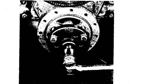
Fig. 20.16. Pulling the crankshaft damper.
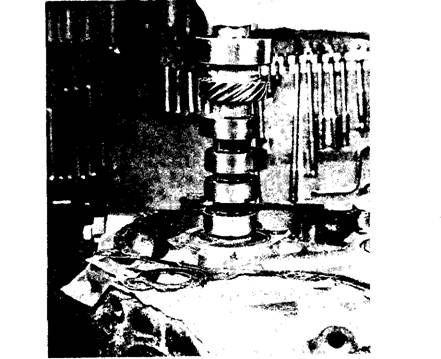
Fig. 20.17. Lifting the camshaft from the block.
The camshaft can be removed at this stage; otherwise it can also be removed after the crankshaft is out. It must be carefully loosened from the engine to avoid damage of the cam bearing or cam lobes and to do this comfortably the front of the engine is pointed up (Fig. 20.17). Since bearing surfaces are soft, they scratch easily, and the cam lobes are hard, so they chip easily.
The main bearing cap should be marked for their position before removal. Since they have been machined in place, they do not perfectly fit in any other location. After marking, they are removed to free the crankshaft. Once the crankshaft is removed, the main bearing caps and bearings are reinstalled to reduce the chance of damage.
