17.12.
Catalytic Converter
The catalytic converter is the best possible device to meet the strict exhaust emission limits. The catalytic converter, which looks like a small muffler is mounted in the exhaust system between the exhaust manifold and the muffler. The converter has no moving parts and forms a chamber for catalyst material in the exhaust systems through which the engine exhaust passes. When the exhaust flows through the catalyst material, the exhaust pollutants are converted into harmless by-products of combustion.
17.12.1.
Emissions Reduction
As described earlier, one way of lowering hydrocarbon (HC) and carbon monoxide (CO) is to raise the combustion temperature, to support more complete burning. But this increases the formation of the third major pollutant, oxides of nitrogen (NOx). The catalytic converter (Fig. 17.69) forms the second method of converting exhaust gas into non-polluting materials. When the exhaust gas passes through a catalyst in the presence of oxygen, the HC and CO compounds combine with the oxygen, giving rise to harmless by-products.

Fig. 17.68. The dual-diaphragm EGR valve.

Fig. 17.69. Typical catalytic converter installation.
A catalyst is a substance, which promotes a chemical reaction without chemically changing itself. For example, the CO and HC in exhaust gas do not normally oxidize unless exposed to oxygen at a temperature exceeding 973 K that is well above the typical exhaust-gas temperature range of673-873 K. In the presence of a platinum catalyst, however, this oxidation process takes place at only 573 K without causing any effect on the platinum.
The Oxidation Reaction.
A catalyst is capable of starting or accelerating a chemical reaction, while it remains unchanged by the reaction and hence is never used up. To change HC and CO into harmless products,.the catalytic elements platinum and palladium start burning reaction with oxygen in the catalytic converter, called on oxidation. Oxidation is the addition of oxygen to a material and in this case the HC and CO combine with oxygen to form H2O and CO2. If enough oxygen is not available in the exhaust, an air pump supplies extra air.
In the oxidation process considerable heat is generated. The temperatures of the catalyst range from 755 to 1145 K, and the exhaust gas at the outlet end of the converter is 10 to 95 K higher than the inlet end. By 1978, car manufacturers were able to reduce the outside, or skin,
temperature of converters by as much as 150 K. This was possible due to the use of smaller engines and changes in engine timing. In spite of the intense heat, however, oxidation does not generate the flame and radiant heat like a simple burning reaction.
The Reduction Reaction.
Since the oxidation catalytic reaction does not have any effect on NOx, a separate reaction, called reduction is required to control NOx. Reduction is the chemical removal of oxygen from a material and hence is the opposite of oxidation. The reduction reaction converts NOx to harmless N2 and CO2 by chemically promoting the removal of oxygen from the NOx to mix with the CO compound. The elements rhodium and platinum are used as reduction catalysts.
As the oxidation and the reduction reactions oppose each other, it is difficult for both to take place at the same time and in the same place. However, an oxidation and a reduction catalyst can be combined in the same converter. A second oxidation catalyst is also necessary for complete emission control. An oxidation-reduction catalyst is called a 2-stage, a 3-way (because it works on all three major pollutants), or a hybrid catalyst. A hybrid catalyst and a second oxidation catalyst can be mounted in opposite ends of the same converter housing or in two separate converters (Fig. 17.70). The hybrid converters were first introduced by Volvo and Saab on a limited number of cars sold in California in 1977.

Fig. 17.70. Catalytic oxidation and reduction reactions.
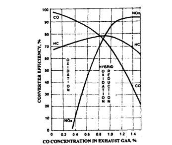
Fig. 17.71. Catalysts operating characteristics.
Exhaust gas first passes through the hybrid converter, where the NOx is converted to N2 and CO2, and then goes through the oxidation converter, where the HC and CO are converted to H2O and CO2. The hybrid converter performs best to reduce NOx when the CO level in the exhaust is between 0.8 and 1.5 percent. As the CO percent increases or decreases from the above valve, the hybrid converter’s efficiency decreases (Fig. 17.71).
17.12.2.
Converter Design Oxidation Converter.
Catalytic converter housing is made of two stamped metal pieces of aluminium or stainless steel, which are welded together to form a round or oval shell. Each shell contains the catalytic element (Fig. 17.72). The aluminised or stainless steel material is used to withstand the high temperatures of oxidation.
Platinum or a mixture of platinum and palladium is used as the catalytic element. These two noble metals best meet the durability, operating temperature, and chemical activity, which are the requirements of an effective catalyst. The catalyst is deposited on an aluminium oxide substrate through which the exhaust gases pass. This substrate with the catalyst layer must withstand high temperature. Two forms of substrate material used are tiny pellets of aluminium oxide and a honeycomb monolith of aluminium oxide. Each form can be either a laminated (sandwiched) design or an extruded design. Both pellets and monolith substrate materials provide several thousand square metres of catalyst surface area over which the exhaust gases flow.
When the pellet substrate is used the gases flow over the top and down through the substrate layers inside the converter shell. With the monolithic substrate material, a diffuser inside the shell causes a uniform flow of exhaust gases over the entire area of the substrate. In the absence of a diffuser, the gases have a tendency to flow only through a central portion of the substrate.
Monolithic substrate material can break easily with a shock or severe jolts. The core, therefore, is placed inside a stainless steel mesh (Fig. 17.72), which provides cushion against mechanical damage. The mesh also protects the core from thermal shock caused by temperature extremes as well as keeps it in proper position during final assembly of the converter shell.
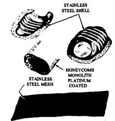
Fig. 17.72. The parts of a typical catalytic converter.
Reduction Converter.
The main differences between the oxidation and the reduction converters are in the type of catalyst used and the positioning of the reduction converter, which is ahead of the oxidation converter in the exhaust system. A typical hybrid converter uses two substrates of different sizes, which are coated with platinum and rhodium. These substrates are covered from all sides by the protective stainless steel mesh and are then enclosed in a stainless steel shell.
17.12.3.
Converter Operating Precautions
There are several ways such as using the wrong fuel, incorrect air-fuel mixtures, and excessive combustion heat due to which a catalytic converter can be damaged or destroyed.
Fuel Requirements.
Cars with catalytic converters must use only unleaded fuel, because the lead and phosphorous additives in leaded petrol considerably reduce the catalyst’s efficiency. If leaded fuel is used, the lead forms a coating over the catalyst so that the exhaust gases are obstructed from reaching the catalyst. Returning at a latter stage to unleaded petrol allows the converter efficiency to be regained only to centain extent. The extent of regaining depends on how long leaded fuel is used. Continued use of leaded fuel generally causes the catalyst to lose its ability to promote oxidation of HC and CO.
As a precaution, the unleaded petrol pump nozzles in service stations and the fuel tank filler necks on cars with catalytic converter are smaller in diameter than those using leaded fuel. In addition, these cars are labelled reading “Unleaded Petrol Only” next to the gas tank filler and on the instrument panel in the driver’s compartment.
Engine Condition.
Excessively high temperatures can reduce converter life and damage the core. Converters perform best at internal temperatures upto 1090 K. At higher temperatures, the catalyst starts to break up or melt. To prevent overheating the converter, proper engine maintenance is necessary. Temperature-protection systems are used on some vehicles, but they work only under certain conditions.
If an engine is in poor condition, or needs a tune-up, the exhaust gas carries a lot of raw fuel. This gas with raw fuel changes the converter to a catalytic furnace. When more than two spark plugs misfire at a time, raw fuel is practically pumped into the catalytic converter. This misfiring if continued for a long time causes the converter internal temperature to rise rapidly.
The improper use of an engine even it is in good operating condition causes an excessive temperature. Long idling periods are one of the worst running conditions as more heat is generated during this period compared to when driving at normal highway speeds. Idle periods of more than 10 minutes are harmful. In this situation, it is advisable to shut off the engine and restart it when required.
Other Precautions.
To avoid excessive catalyst temperatures and the possibility of fuel vapours reaching the converter, the following may be observed.
(i) Avoid starting the engine on compression by pushing the vehicle. Instead use jumper cables.
(») Avoid cranking an engine for more than 60 seconds when it is flooded or firing intermittently.
(Hi) Avoid turning off the ignition switch when the car is in motion.
(iv) Attend immediately the troubles such as engine dieseling, heavy surging, repeated stalling or backfiring, and other such indications of below-normal performance.
(v) Avoid disconnecting spark plugs to test the ignition whenever required. If an oscilloscope is not available, avoid running the engine for more than 30 seconds with the plug wire off or shorted.
17.12.4.
Oxidation Converter Applications
Regulations require that a catalytic converter should run perfectly for at least 80,000 kms without requiring any service. All oxidation converters are installed between the engine and the muffler, and reduction converters between the engine and the oxidation converter. Most converters are placed under the passenger compartment and are connected to the exhaust system in one of three methods. These include bolt-together flange (Fig. 17.73), slip fit with a clamp (Fig. 17.73), or welded to the exhaust pipes.
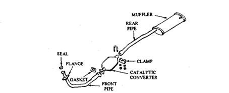
Fig. 17.73. Catalytic converter installed with a bolted flange at one end and a clamp at the other.
All single exhaust systems generally have only one converter. Duel exhaust systems may have a converter on one side only or a separate converter on each side (Fig. 17.74). The oxidation converters used by some automobile manufacturers are presented below.
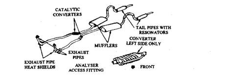
Fig. 17.74. Dual exhausts system with two catalytic converters.
American Motors and General Motors Systems.
AMC and GM cars installed pellet converters manufactured by the AC Division of General Motors (Fig. 17.75). This converter housing is insulated, so it remains at almost the same temperature as the outside of the muffler. Only a few cars, such as the Corvette (Fig. 17.76) require a heat shield. The pellet catalyst, in this system, can be removed from the converter housing through a drain plug using a special equipment and can be replaced with a fresh catalyst charge after 80,000 kms run or if the catalyst material is deteriorated.
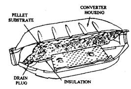
Fig. 17.75. AC pellet-type catalytic converter.
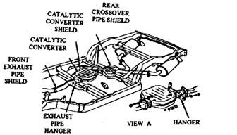
Fig. 17.76. Catalytic converter installed with a heat shield.
Chrysler Systems.
Chrysler cars incorporate the monolithic converter (Fig. 17.77), which requires the replacement of total unit in case of damage or after 80,000 kms run. This type of converter transfers a lot of heat through the housing and so heat shields (Fig. 17.78) are installed to safeguard the passenger compartment, the automatic transmission and its cooler lines, the torsion bars, the rear shock absorbers, and other chassis components.
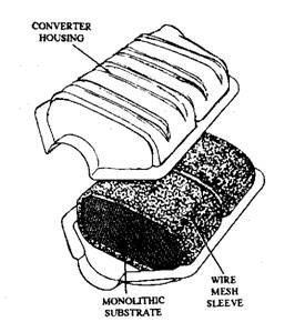
Fig. 17.77. Catalytic converter with a monolithic substrate (Chrysler)
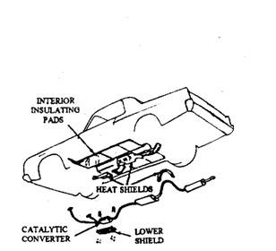
Fig. 17.78. Catalytic converter heat shield installation. (Chrysler).
Size, shape, and placement period of these shields depends on the car model. The under body floor pan above the converter is heavily shielded, and more heat insulation is also placed under the floor mats. Car modeh having both a converter and an air pump system use even more shielding, because the air pump increases the operating temperature of the converter. Also these cars use a protective grill guard under the converter so that direct contact of housing with
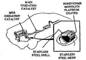
Fig. 17.79. Mini-converter installation (Chrysler).
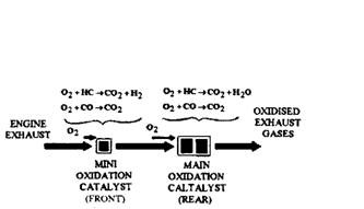
Fig. 17.80. Two stage oxidation reaction in mini-converter (Chrysler).
burnable materials is prevented. The grill also supports cooling of the converter housing by radiating heat to the air flow beneath the car.
On some 1977 and later models, Chrysler incorporated a small oxidation-type converter, called an underhood unit and was welded into the engine exhaust pipe 150 to 300 mm away from the exhaust manifold (Fig. 17.79). This minicatalytic converter is of the same design as the main converter and is used alongwith the main underfloor converter. The mini-converter starts the oxidation of HC and CO before they reach the main underfloor, resulting in more complete oxidation of the exhaust gas (Fig. 17.80).
Some 1975 models use a catalyst protection system (CPS) (Fig. 17.81), which prevents fuel from reaching the converter during closed-throttle deceleration after high-speed cruising. When the CPS electronic speed switch senses approximately 2,000 rpm engine speed, the switch energizes a throttle positioner solenoid to extend its plunger.
If the accelerator pedal is released when engine speed is above 2000 rpm, the solenoid plunger holds the throttle valve open at the fast idle position. This causes intake air to balance the air-fuel mixture and to speed up combustion so that the converter is protected against overheating. Once engine speed drops below 2000 rpm, the speed switch deenergizes the solenoid, and the throttle returns to a normal slow-idle position as the the solenoid plunger retracts. The CPS system was discontinued as a running change on 1975 models.
Ford Systems.
Ford cars have a monolithic converter (Fig. 17.82). Some 1977 and later models have used converters with two monolithic substrates (Fig. 17.83). The entire converter unit is replaced after 80,000 kms run or in case of damage.
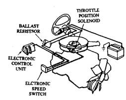
Fig. 17.81.Catalyst protection system (Chrysler).
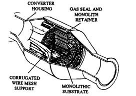
Fig. 17.82. Catalytic converter with monolithic substrate (Ford).

Fig. 17.83. Single and dual-substrate catalytic converter (Ford).
Converters are located underneath the seating area floor pan on some models, and under the toe-board area on other models. Since a high amount of heat is transferred through the housing by this type of converter, various formed and perforated exhaust shields are welded or clamped in place, suiting to the particular model.
The Ford catalytic converter system requires a secondary air source to supply enough oxygen to the exhaust for complete oxidation of the HC and CO. This is provided by the Thermactor air injection system (Fig. 17.84). This injection system protects catalyst from overheating.
A 2-port solenoid vacuum valve (Fig. 17.85) of normally closed type, replaces a normally open valve of the same type used before 1975 with other Ford emission systems. This new valve like the older one opens and closes the vacuum circuit in response to an electrical signal. The solenoid vacuum valve controls the vacuum to a vacuum differential valve (VDV) and thereby controls the air-bypass operation of the diverter valve.
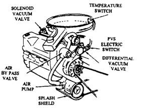
Fig. 17.84. Air injection system supplies extra air to the catalytic converter (Ford).

Fig. 17.85. Solenoid valve controls vacuum to a injection diverter valve in catalytic converter (Ford).
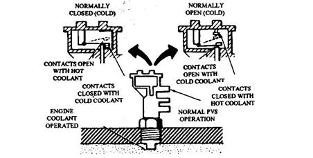
Fig. 17.86. Electric ported vacuum switch is used in catalytic converter air injection systems (Ford).
Depending on the car model, the solenoid vacuum valve is energized in various ways. Some vehicles use a temperature switch in the air cleaner. Vehicles with catalyst protection use a floor-mounted switch, or either a normally open or a normally closed electric ported vacuum switch (PVS) (Fig. 17.86). The switch works with the solenoid vacuum valve for bypass operation of the diverter valve when coolant temperature becomes 385 K or more.
A floor-mounted switch or a PVS is used to activate the solenoid vacuum valve which allows the vacuum differential valve to temporarily dump vacuum to the diverter valve during decelaration. The vacuum valve also prevents backfire if the exhaust mixture is too rich. In each case, the vacuum differential valve prevents overheating of the converter and so also damaging of catalyst.
17.12.5.
Oxidation-reduction Converter or Three-way Catalytic Converters
The catalytic converters described in the section 17.12.4 are all oxidation converters. In 1977, Volvo and Saab introduced the first oxidation-reduction converters to control all three major exhaust emissions. In 1978, Ford and General Motors installed hybrid, or 2-stage, converters or three-way catalytic converters to control HC, CO and NOx. These Converters are commonly used today.
At stoichiometry there is just the right amount of oxygen available to burn the entire hydrocarbon. If an engine can be operated at all times with an air-fuel ratio close to stoichiometry then it is possible to use a catalytic converter to clean the exhaust gases by first removing the oxygen from the NOx a process of chemical reduction and then using this liberated oxygen to oxidize the CO and HC. The vehicle’s exhaust gases then contain only CO2, H2O and N2, all of which are harmless constituents of air. Such a catalytic converter is called a three-way catalyst (TWC) since it removes all three pollutants.
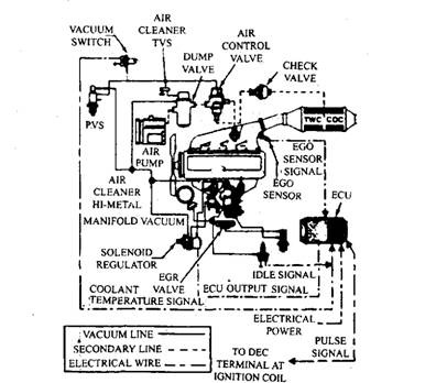
Fig. 17.87. Three way converter on 4-cylinder engines (Ford).
Ford Systems.
The 2.3 litre, 4 cylinder engine installed in California Pintos and Bobcas during 1978 uses a closed loop, feedback emission control system (Fig. 17.87). This system contains an oxidation-reduction catalytic converter, an electrically controlled carburettor and an exhaust gas oxygen sensor. The front half of the converter contains an oxidation-reduction catalyst to control HC, CO and NOx using platinum and rhodium as catalyst on a monolithic substrate. The rear half of the converter has only a platinum catalyst to further oxidize HC and CO.
The oxygen sensor continuously monitors the unburned air-fuel ratio in the exhaust and provides closed loop feedback. The electronic control module receives this signal in addition to the signals from a throttle angle switch, two vacuum switches, and the ignition control side of the ignition coil. The module sends a signal to the solenoid regulator, which controls the vacuum supply to the carburettor power valve, so that the precise control of the intake air-fuel ratio required by the hybrid converter is maintained.
During engine warm-up, the air injection pump supplies extra air to the exhaust manifold and hence it passes through the converter. Once the engine attains operating temperature, a vacuum signal from the temperature vacuum switch redirects the air injection to the middle of the converter. The extra air is then supplied only to the oxidation catalyst in the rear half of the converter.
General Motors Systems.
A closed loop feedback emission control system is also used on some GM’s 1978 California small cars. The operation of this system is almost same as that of Ford system. It is installed on all 1978 California Sunbirds with the 151-cid 4-cylinder engine, as well as some Skyhawks with the 231-cid V-6. This is the first production use of a closed-loop system on a V-type engine.
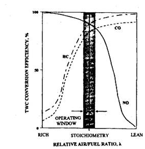
Fig. 17.88. Conversion efficiency of the three-way catalytic converter as a function of relative air-fuel ratio.
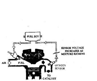
Fig. 17.89. Use of closed loop control system to maintain air-fuel ratio at 14.7 :1.
17.12.6.
Performance of Three-way Catalytic Converters
The purification characteristics of the three-way catalysed (TWC) vary widely depending on the operating air-fuel ratio of the engine (Fig. 17.88). Optimum pollutant elimination occurs for mixtures very close to stoichiometry. With a variation of about ± 0.1 of stoichiometric air-fuel ratio, i.e. at X = 1.00 ± 0.01 approximately, the conversion efficiency of 90% may be achieved. This narrowness in the variation of A is beyond the control range of mechanical systems such as ordinary carburettors. A TWC emission control system therefore requires a closed loop electronic air-fuel ratio control system. An exhaust gas oxygen sensor (EGO sensor) is used in this control system to provide an electrical feedback signal indicating the composition of the exhaust gas. An electronic control unit then adjusts the amount of injected fuel to achieve the required air-fuel ratio (Fig. 17.89). This sort of control maintains the mixture close to stoichiometric for all driving conditions and so emissions are held to a minimum.
17.12.7.
Structure of the Three-way Converter
A typical TWC structure, illustrated in Fig. 17.90, consists of a catalytic element mounted in a metal casing, which forms part of the exhaust system. The position, size and amount of catalyst used depend on the engine type and operating conditions.
Since all of the exhaust gas must come into contact with the catalyst surface for proper reaction, it is quite necessary that a thin layer of active material is spread over a large area. Most converters, therefore, use a fine ceramic honeycomb structure, with passageways, about
1 mm , onto which a thin wash coat of the catalytic metal is deposited. Catalytic material forms only about 10% of the weight of the element, but it is applied over a surface area of several hundred square metres with a gas capacity of 1-2 litres.
In most converters platinum (Pt) is used for the oxidation of HC and CO, and rhodium (Rh) for NOx reduction. Nickel (Ni) and cerium (Ce) may also be added to improve performance. Alumina (AI2O3) is used as the supported ceramic.
Catalytic action does not take place until the exhaust gases heat the element to about 623 K (light-off temperature) and so a cold vehicle must be driven for several minutes before emission control can start. Even then, it is possible that the catalyst can have a warmed-up before the cold engine can run smoothly with a stoichiometric mixture. Under these circumstances the engine is supplied with an enriched mixture and extra air (secondary air) is pumped into the converter so that it can function until the engine is warm enough to accept stoichiometric fuelling.
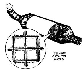
Fig. 17.90. Structure of typical catalytic converter.
