Global Positioning System Reference
In-Depth Information
Incoming signal
Incoming signal
Generated signals
Generated signals
Early
Early
Prompt
Prompt
Late
Late
Correlation
Correlation
1
1/2
0
L
P
1
1/2
0
P
E
L
E
−
1
−1/2
0
1
Chips
−1
−
1/2
0
1/2
1
Chips
(a)
(b)
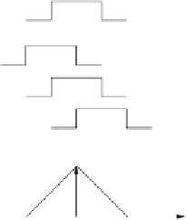
FIGURE 7.11. Code tracking. Three local codes are generated and correlated with the
incoming signal. (a) The late replica has the highest correlation so the code phase must be
decreased, i.e., the code sequence must be delayed. (b) The prompt code has the highest
correlation, and the early and late have similar correlation. The loop is perfectly tuned in.
be decreased. In Figure 7.11b the highest peak is located at the prompt replica,
and the early and late replicas have equal correlation. In this case, the code phase
is properly tracked.
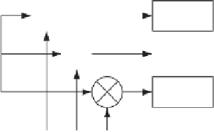
The DLL with three correlators as in Figure 7.10 is optimal when the local
carrier wave is locked in phase and frequency. But when there is a phase error on
the local carrier wave, the signal will be more noisy, making it more difficult for
the DLL to keep lock on the code. So instead the DLL in a GPS receiver is often
designed as in Figure 7.12.
Integrate
& dump
I
E
E
I
Integrate
& dump
I
P
P
Integrate
& dump
I
L
L
Incoming
signal
Local
oscillator
PRN code
generator
L
90°
Integrate
& dump
Q
L
P
Q
Integrate
& dump
Q
P
E
Integrate
& dump
Q
E
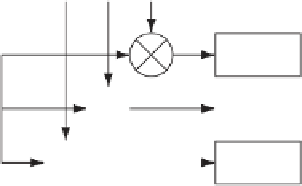
FIGURE 7.12. DLL block diagram with six correlators.


Search WWH ::

Custom Search