Global Positioning System Reference
In-Depth Information
Q
ϕ
ϕ
I
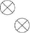
FIGURE 7.9. Phasor diagram showing the phase error between the phase of the input
carrier wave and the phase of the local carrier wave replica.
7.5
Code Tracking
The goal for a code tracking loop is to keep track of the code phase of a specific
code in the signal. The output of such a code tracking loop is a perfectly aligned
replica of the code. The code tracking loop in the GPS receiver is a delay lock loop
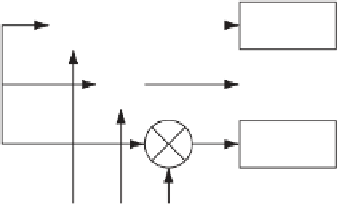
(DLL) called an early-late tracking loop. The idea behind the DLL is to correlate
the input signal with three replicas of the code seen in Figure 7.10.
The first step in Figure 7.10 is converting the C/A code to baseband, by multi-
plying the incoming signal with a perfectly aligned local replica of the carrier
wave. Afterwards the signal is multiplied with three code replicas. The three
replicas are nominally generated with a spacing of
1
2
chip. After this second
multiplication, the three outputs are integrated and dumped. The output of these
integrations is a numerical value indicating how much the specific code replica
correlates with the code in the incoming signal.
The three correlation outputs
I
E
,
I
P
,and
I
L
are then compared to see which one
provides the highest correlation. Figure 7.11 shows an example of code tracking.
In Figure 7.11a the late code has the highest correlation, so the code phase must
±
Integrate
& dump
I
E
E
Incoming
signal
I
Integrate
& dump
I
P
P
Integrate
& dump
I
L
L
Local
oscillator
PRN code
generator
FIGURE 7.10. Basic code tracking loop block diagram.


Search WWH ::

Custom Search