Chemistry Reference
In-Depth Information
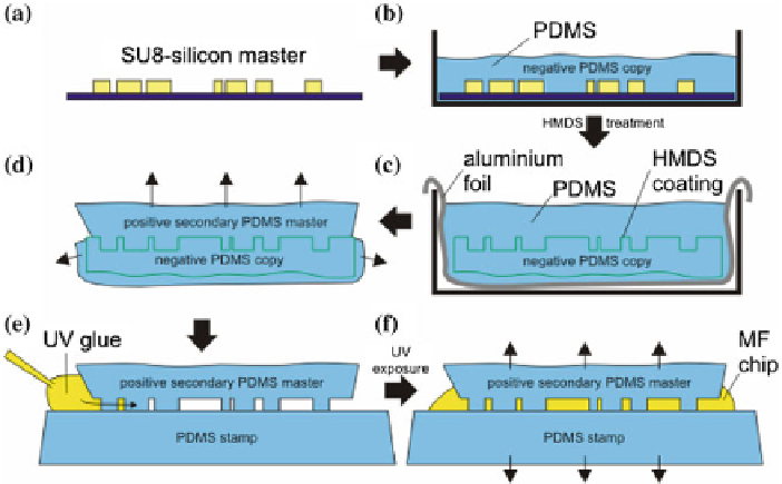
Fig. 4.2
To protect the SU8 masters (
a
) a three step copying technique is used for the microfluidic
chip production. After preparing a negative PDMS copy of the channel structure (
b
) its surface is
treated with HMDS and a secondary (positive) PDMS master is taken (
c
). This secondary master
is separated from the surrounding PDMS (
d
) and placed on a flat PDMS stamp (
e
). The spaces in
between are filled with UV curable glue and after 5-10min of UV light exposure the microfluidic
chip can be peeled off (
f
)
a few hundred micrometers assuming a planar orientation, i.e. no curvature, of the
film. Nevertheless, these reconstituted membranes also show the drawback that the
Plateau Gibbs border (PGB), the oil containing reservoir surrounding the membrane
patch, will always be in the path of the X-rays. Due to the strong diffractive index
contrast between the water and the PGB it is likely to give an additional contribution
to the diffraction pattern. This is expected to make the theoretical modeling more
complicated—however, for the work shown here, we do not yet include this effect
into the model. It must be noted that this is not the case for the bulged interface of
the BLMs where the theoretical modeling of the interface is thus less complicated.
4.3 Results
4.3.1 Phase Contrast Imaging Model
Quantitative structural and dynamical studies of microfluidic lipid membranes were
performed by using a direct imaging method, namely propagation based X-ray phase
contrast imaging (PCI). To this end a simplified model is introduced that explains