Chemistry Reference
In-Depth Information
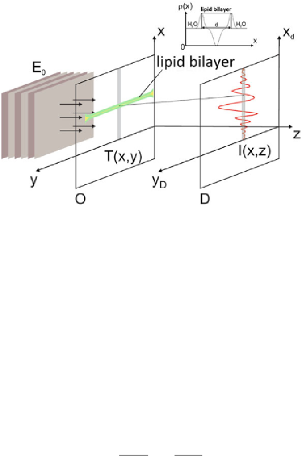
Fig. 4.3
The mfBLM at position
O
is described by a transmission function
T
(
x
,
y
)
obtained by
projection of the electron density
ρ(
x
)
along the z-axis. After free space propagation of the exit
wave over a distance
z
along the optical axis, a Fresnel interference pattern
I
(
x
)
is recorded in the
detector plane
D
, representing a phase contrast image of the projected density profile
the image formation of lipid membranes.
1
It is instructive to first study the problem
in the context of a parallel beam geometry and extend the same to a divergent beam
setup in the next section. We describe the propagation of wave fields interacting with
this model system in the case of the Fresnel regime, comparable to Gabor's in-line
holography.
We now consider a simplified scheme of the membrane that can be included in
the underlying equations being elucidated later. This model is shown in Fig.
4.3
.In
the case of a swollen membrane of thickness d, that still includes organic solvent, we
assume the electron density
to be constant across themembrane. It is regarded as the
most relevant parameter describing the scattering properties of X-rays in an object.
In the following the dispersive part
ρ
δ
of the complex refractive index
n
=
1
−
δ
+
i
β
,
instead of the electron density
ρ
, will be used. Both parameters are related as follows
[
17
,
18
]:
2
n
e
r
0
2
δ
=
λ
N
A
Z
ρ
n
e
=
(4.1)
π
A
with the wavelength
, classical electron radius
r
0
, Avogadro's number
N
A
,atomic
number
Z
, atomic weight
A
, and the electron density number
n
e
(including the mate-
rial's density
λ
, that is induced by the propagation
of the X-rays through the membrane, shall be derived. Based on the definition of thin
phase objects, which is given in [
19
-
21
], we assume the extension of the membrane
ρ
). In the following the phase shift
φ
1
Model developed by Michael Mell