Graphics Reference
In-Depth Information
V
s
=
C
P
V
V
k
=
C
P
t
s
2
s
2
t
=
C
k
<
t
r
indicates penetration
with bounding sphere
s
r
P
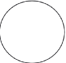
FIGURE 11.5
Testing for potential collision with a bounding sphere.
2
r
2
C
P
k
=
r
2
=
s
2
t
2
k
2
=
s
2
(
C
P
t
)
2
k
2
=
r
2
t
2
(
C
P
t
)
2
k
2
=
r
2
t
2
2
t
2
(
C
P
2
C
P
t
V
K
2
r
2
C
P
2
t
=
2
C
P
U
r
2
t
2
s
=
B
r
C
P
C
P
U
=
W
C
s
k
t
(
U
U
(
U
V
)
U
V
)
W
=
P
B
=
P
(
C
P
t
)
U
sW
FIGURE 11.6
Calculation of point
on the boundary of a sphere.
B
When a potential collision has been detected, the steer-to-avoid procedure can be invoked. It is use-
ful to calculate the point,
B
, on the boundary of the bounding sphere that is in the plane defined by the
direction vector,
V
, the location of the flock member,
P
, and the center of the sphere,
C
. The point
B
is
located so that the vector from
P
to
B
is in the plane defined earlier, is tangent to the sphere, and is on the
Steering to the boundary point on the bounding sphere is a useful strategy if a close approach to
the object's edge is not required. For amore accurate andmore computationally expensive strategy, the flock
member can steer to the silhouette edges of the object that share abackface anda front facewith respect to the
flockmember's position and, collectively, define a nonplanarmanifold. Faces can be tagged as front or back
by taking the dot product of the normalwith a vector fromthe flockmember to the face. The closest distance
between the semi-infinite direction of the travel vector to a silhouette edge can be calculated. If there is


Search WWH ::

Custom Search