Graphics Reference
In-Depth Information
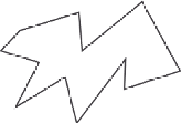
Silhouette edges
Closest point on silhouette edge
Flock member
Direction of travel
FIGURE 11.7
Determining steer-to-point from silhouette edges.
space for the flock member's body and a comfort zone in which to fly around this point, then this point can
be steered toward that closest point on the silhouette (
Figure 11.7
)
.
An alternative strategy is to sample the environment by emitting virtual feelers to detect potential
collision surfaces. The feelers can be emitted in a progressively divergent pattern, such as a spiral, until
a clear path is found.
Another strategy is to model vision by projecting the environment to an image plane from the point
of view of the flock member. By generating a binary image, the user can search for an uncovered group
of pixels. Depth information can be included to allow searching for discontinuities and to estimate the
size of the opening in three-space. The image can be smoothed until a gradient image is attained, and
the gradient can be followed to the closest edge.
Splitting and rejoining
When a flock is navigating among obstacles in the environment, one of theirmore interesting behaviors is
the splitting and rejoining that result asmembers veer in different directions and break into groups as they
attempt to avoid collisions. If the groups stay relatively close, then flockmembership urges can bring the
groups back together to re-form the original single flock. Unfortunately, this behavior is difficult to pro-
duce because a balance must be created between collision avoidance and the flock membership urge,
with collision avoidance taking precedence in critical situations. Without this precise balance, a flock
faction will split and never return to the flock or flock members will not split off as a separate group;
instead they will only individually avoid the obstacle and disrupt the flock formation.
Modeling flight
Since flocking is often used to model the behavior of flying objects, it is useful to review the principles
of flight. A local coordinate system of
roll
,
pitch
, and
yaw
is commonly used to discuss the orientation
of the flying object. The roll of an object is the amount that it rotates to one side from an initial ori-
entation. The pitch is the amount that its nose rotates up or down, and the yaw is the amount it rotates
about its up vector (see
Figure 11.8
)
.
Specific to modeling flight, but also of more general use, is a description of the forces involved in
aerodynamics.
Geometric flight
, as defined by Reynolds [
34
]
, is the “dynamic, incremental, rigid trans-
formation of an object moving along and tangent to a three-dimensional curve.” Such flight is con-
trolled by
thrust
,
drag
,
gravity
, and
lift
(
Figure 11.9
)
. Thrust is the force used to propel the object


Search WWH ::

Custom Search