Graphics Programs Reference
In-Depth Information
It is possible to change the names and paths of these new files to
suit your needs.
It is a good idea to
give unique names
to the frame subas-
sembly and skeleton
when prompted.
Filename prompting
can also be disabled.
Inserting Members Between Points
Rather than creating a lot of extra lines or model edges, you can place the mem-
bers by selecting a start point and an end point.
1.
Make certain that the 2013 Essentials project file is active, and then
open the
c11-02.iam
file from the
Assemblies\Chapter11
folder.
2.
Switch the Ribbon to the Design tab, and start the Insert Frame tool
from the Frame panel.
3.
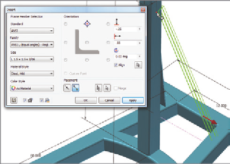
In the Insert frame dialog box, set Standard to ANSI, Family to ANSI
L (Equal angles) - Angle steel, and Size to L 1.5 × 1.5 × 3⁄16, keeping
the orientation in the center of the profile.
4.
Make sure the Insert Members Between Points Placement option is
active, and click the end point of the dashed, pink line and the line con-
cealed in the upright member of the frame, as shown in Figure 11.4.
Selection points
must be in a sketch.
If there is a work
point in the model
you want to use, you
will need to project
it into a sketch first.
5.
Change the orientation of the profile to the top-center option, as shown
in Figure 11.4.
6.
Click the Align option and pick the centerline of the 28-inch member.
Then set the offset values to -.25 and .55, as shown in Figure 11.4.
7.
Click OK to generate the frame members, and then click OK to approve
the names of the new file.
FIGURE 11.4
Placing a frame member by clicking two points
The ability to realign the profile gives you flexibility with open metal shapes.


Search WWH ::

Custom Search