Graphics Programs Reference
In-Depth Information
3.
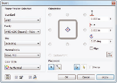
In the Insert frame dialog box, set Standard to ANSI, Family to ANSI
AISC (Square) - Tube, and Size to 3 × 3 × 3⁄16, with the orientation
in the center of the profile, as shown in Figure 11.2.
4.
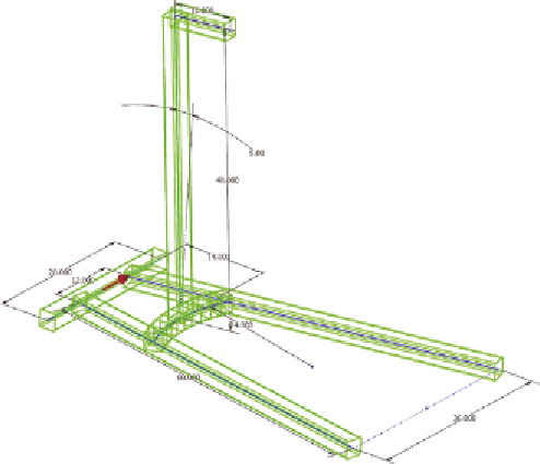
Make sure the Insert Members On Edges Placement option is active,
and click all the black lines (and only the black lines) on the skeleton.
Your results will look like Figure 11.3.
5.
Click OK to generate the frame members; then click OK again to
approve the creation of the new files and a third time to approve the
names of the new files.
FIGURE 11.2
Setting the type of metal section
FIGURE 11.3
A preview of the steel components to be
placed in the frame
Search WWH ::

Custom Search