Graphics Programs Reference
In-Depth Information
4.
Open the Shape tab in the dialog box. Click the Flip Beam Direction
button, and notice the change to the preview. If the original preview
showed the hooks correctly positioned (protruding from the cover),
click the Flip Beam Direction button again.
5.
Return to the Hook tab. Notice the green arrows; the arrows indicate
the direction of the hook. One of them points inward. Click that arrow
until both hooks are pointing outward.
6.
Switch to the Beam tab of the dialog box.
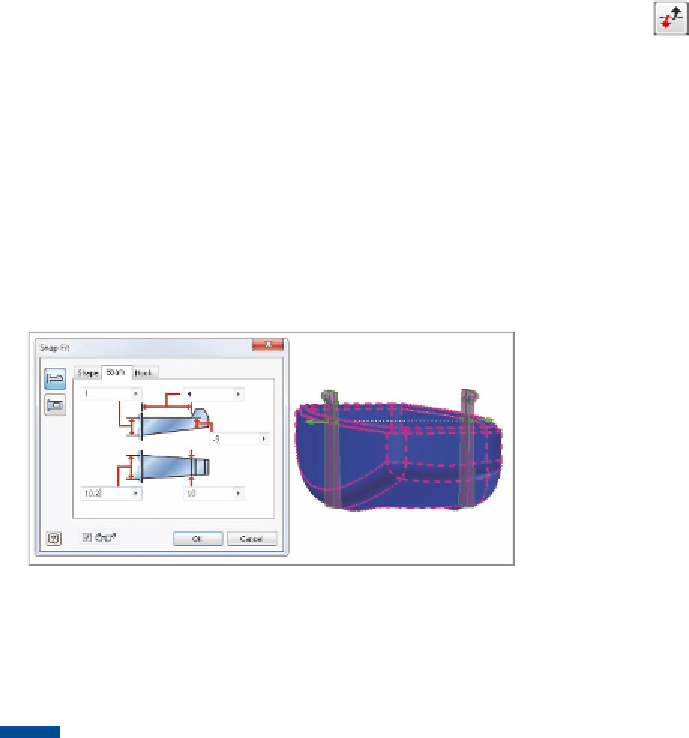
7.
Match your dialog box values to those in Figure 9.13, and click OK to
build the features.
FIGURE 9.13
The Snap Fit tool creates complex geometry easily.
The loop side of a snap fit is placed in the same way. In general, all the plastic
features follow a common process that makes them easy to learn.
TIP
Another advantage of using a multibody solid is not having to
reenter size information to create mating plastic features. The feature
remembers the options changed in the active file.
Adding Ribs
The Rib tool is not a specialized plastic part feature, but it is common in plastic
parts. Ribs are used in many types of parts, and the Rib tool can be used to cre-
ate a rib or a web; you have the ability to control the width and depth.
1.
Verify that the 2013 Essentials project file is active, and then open
c09-11.ipt
from the
Parts\Chapter9
folder.
2.
Orbit the model so that you can clearly see the open portion.
Sketched in the interior of the front part is a series of lines that will
locate the ribs. Those lines do not extend to the edges of the part and


Search WWH ::

Custom Search