Graphics Programs Reference
In-Depth Information
Holding the Ctrl key is necessary only if you want to start a design
accelerator with the default options.
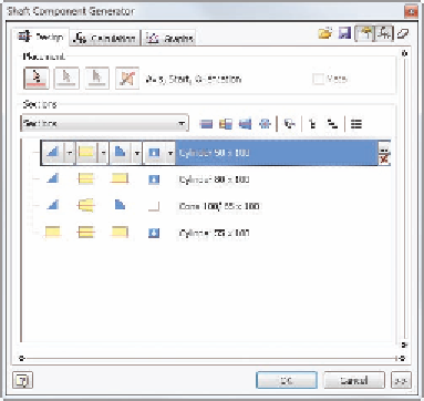
When the dialog box (Figure 8.6) opens, shaft sections appear in
the large window in the dialog box. Each segment row has columns
for the left and right end treatments, the section shape, and any spe-
cial additions. The size and shape are listed to the right as well.
FIGURE 8.6
The Shaft Generator dialog box
showing the default shaft segments
3.
Select the top segment. At the far right, click the Delete icon, and
then click Yes in the dialog box that appears.
4.
Delete all but the segment listed as Cylinder 55 × 100.
5.
Double-click the description of this segment.
6.
Change the D (diameter) and L (length) values to 10 mm by clicking
the current values in the Cylinder dialog box that appears.
7.
Click OK to update the size of the segment.
8.
Locate and select the Insert Cylinder icon just above the updated
section.
9.
This will insert a duplicate segment below the original. Edit the size
of the new segment to D = 12, L = 3, and click OK.
10.
Click the Insert Cylinder tool again, and create a new segment with
D = 25 and L = 12 values.


Search WWH ::

Custom Search