Information Technology Reference
In-Depth Information
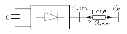
STATCOM and the system connection diagram were shown in Figure 3. The
fundamental voltage amplitude of inverter output was
V
ASV G
, system voltage is
V
S
, compensation current is I.
Fig. 3.
STATCOM and the system connection diagram
STATCOM adopted voltage bridge circuit, therefore it must be incorporated
into the system by connecting the reactor or transformer. The function of reactor
first is to connect the inverter and AC bus of different voltage; second inhibition
of the high harmonic currents. X in figure is equivalent for leakage inductance or
connection reactance, r is equivalent for copper consumption and active power
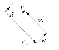
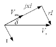
loss of STATCOM. STATCOM is represented as an ideal synchronous condenser,
the steady-state operation the vector diagram shown in Figure 4.
(a) Inject reactive power to
the system
(b) Absorb reactive power
from the system
Fig. 4.
the phasor diagram of STATCOM steady state operation
Known from the phasor diagram, STATCOM injected reactive power into sys-
tem:
Q
ASV G
=
±IV
S
cos
δ
(1)
In formula,
δ
is the angle of phasor
V
ASV G
lag in vector
V
S
,
δ>
0 corresponds
to a positive sign,
δ<
0 corresponds to the negative sign. The amplitude of the
compensation current:
V
S
r
sin
δ
I
=
∓
(2)

Search WWH ::

Custom Search