Information Technology Reference
In-Depth Information
4 Simulation System and Anylysis
In this paper a simulation example using improved IEEE9 node system, the
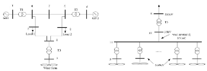
wind farm access system topology shown in Figure 5. Topology of the wind
farm integrating system was shown in Figure 6. Wind farm capacity is 84MW,
the master device fan using GE1.5MW from the United States, rated terminal
voltage 0.69kV, rated power of 1.5MW and rated frequency of 50Hz, the re-
active power regulation range -0.73-0.49Mvar.Each wind turbine with a step-up
transformer connected to the collector bus, than through VSC-HVDC or HVAC,
offshore wind farm can access to the step-up substation on land, that is the main
power grid.
Fig. 5.
topology of wind farm integrate to
system
Fig. 6.
Wind Farm tie line diagram
Simulate the improved IEEE9 node system in PSS / E software, the wind
farm model using PSS / E fan package of GE doubly-fed wind turbine model.
It uses the rotor AC excitation to the rotor excitation current by the PWM
controller, this generator can be in a certain wind speed range. This article did
not simulate wind speed, so the rated wind speed 14m/s, the output power was
the rated power. The entire system has reached steady state at t = 0. No.8
bus occurred three-Phase short-circuit fault at t=1s, fault continued for 0.1s,
and cleared at t=1.1s. Observing the voltage of bus 11 high-pressure side of
offshore wind farm step-up substation and bus 8 fault occurred shown in Figure 7,
Figure 8.
STATCOM can be applied to improve dynamic recovery characteristics of
wind farm under the integration method of HVAC. STATCOM installed in bus
10, the capacity is
30Mvar. Bus 8 occurred three-Phase short-circuit fault at
t=1s, fault continued for 0.1s, and cleared at t=1.1s. The simulation results
shown in Figure 9, under normal operating conditions, STATCOM can appro-
priately improve the voltage as well as the recovery speed, so it can improve
fault ride through capability.
±
Search WWH ::

Custom Search