Biomedical Engineering Reference
In-Depth Information
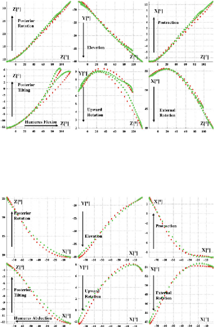
Fig. 9.10
ShRm modeling results during humeral displacement in the sagittal plane.
To p ro w
Clav results.
Bottom row
Scap results. All results are given according to Hum Z-axis rotation
(flexion/extension) in the thoracohumeral frame.
Green
and
red dots
correspond to humerus flexion
and extension, respectively. Two motion cycles are given
Fig. 9.11
ShRm modeling results during humeral displacement in the frontal plane.
To p ro w
Clav
results.
Bottom row
Scap results. All results are given according to Hum X-axis rotation (adduc-
tion/abduction in the thoracohumeral frame.
Green
and
red dots
correspond to humerus abduction
and adduction, respectively. Two motion cycles are given