Biomedical Engineering Reference
In-Depth Information
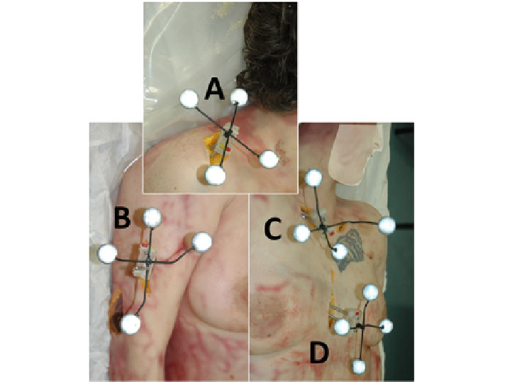
Fig. 9.4
Drilling of TF with reflective markers in the bony segments of a fresh-frozen specimen
(this illustration is made of 3 snapshots, right anterolateral view).
A
scapula TF inserted in the
acromion.
B
humerus TF drilled in the bone shaft.
C
clavicle TF.
D
thorax TF inserted in the sternal
body. Each TF was secured to the underlying bones using two small surgical pins to increase the
TF fixation. Skin and muscle incisions were kept as minimal as possible to reduce possible motion
artefacts due to soft tissue dissection
Once the 3Dmodels were available, virtual palpation was performed to determine
spatial locations of all palpable ALs on the 3D models [
50
]. Such ALs serve three
purposes:
(1) to allow approximation of geometrical joint centre (for example, for the humerus
head);
(2) to allow registration of bone to motion during motion analysis; and
(3) to allow creation of anatomical frames.
Spatial coordinates of all palpated landmarks were also given in the original global
frame of the medical imaging system. The same palpation procedure was applied for
ex-vivo and in-vivo data.
After CT imaging, the specimen was secured within a special jig in a sitting
position in order to align gravity along the conventional anatomical planes (i.e., the
gravity vector ran perpendicular to the shoulder horizontal plane). Before movement
data capture, the joint was manually set in neutral position (arm along the thorax,