Biomedical Engineering Reference
In-Depth Information
Receivers
(b)
Receivers
(a)
Driver
Driver
Z
Z
t
t
R
term
R
term
(d)
Receivers
(c)
Receivers
Vcc
Driver
Driver
Z
t
Z
R
t
term
R
term
R
term
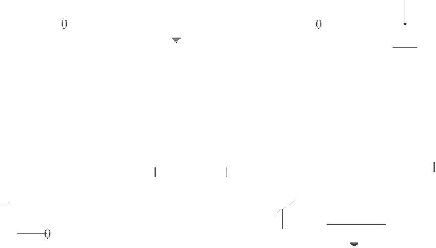
Figure 4.38
Transmission line termination techniques: (
a
) series termination; (
b
) parallel termination; (
c
) Thévenin termination; (
d
) ac
termination.
Driver Output
Received Data
a
Skewed Stream
Parallel
Data Bus
b
c
=
<
a
c
b
Error
Figure 4.39
Unequal lengths of PCB track on a parallel bus will cause skew between the pulse streams, leading to reception errors.
the skew induced in bit sequences sent along parallel paths of di
erent lengths can cause
errors in the communication between circuits, especially when transmitter and receiver cir-
cuits are placed in di
ff
erent boards interconnected through backplanes or ribbon cables.
The obvious solution is to keep parallel paths as short as possible and ensure equal PCB
track lengths for all parallel paths.
Skew also deserves very serious consideration in the design of high-speed micro-
processor clock distribution networks. In general, all logic computation during a single
clock cycle has to be performed within the very short time left over by the delays su
ff
ff
ered


Search WWH ::

Custom Search