Biomedical Engineering Reference
In-Depth Information
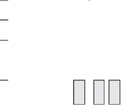
V
receiver
Ideal Leading-Edge
5V
V
HI
MIN
Received Step + Re-reflection
V
MA X
LO
0
Time
Received Data:
“1”
“0”
Figure 4.37
A critical length of PCB track could cause the rereflected pulse to distort the lead-
ing edge of the pulse so much that it will cause, in this case, the false detection of a logic-low.
to be positive, possibly causing the false detection of a logic-high, or the false activation
of an edge-sensitive device. Moreover, a re
fl
ected pulse presented to the receiver will cause
yet another re
ected pulse, which although with far less amplitude, may still be able to
cause erroneous operation of a circuit.
Obviously, the solution to the re
fl
ected-pulse problem is to match the impedances in
the best possible way. This design procedure, called
transmission line termination
, can
be accomplished in four di
fl
erent ways: series, parallel, Thévenin, and ac, as shown in
Figure 4.38. Series termination is recommended whenever
Z
d
ff
Z
t
and the line is driving
a reduced number of receivers. This technique, which gives good results in most high-
speed TTL circuits, consumes negligible power and requires the addition of only one
resistor, the value of which is given by
R
term
Z
t
Z
d
The major drawback of the series termination technique as far as logic signal integrity goes
is that it increases signal rise and fall times. However, the same is a blessing as far as
reducing electromagnetic emissions.
In contrast to series termination, which eliminates pulse re
fl
ection at the driver end, all
other techniques eliminate re
fl
ection at the receiver end of the PCB track. Parallel termi-
2
Z
t
techniques consume large
amounts of power; however, they provide very clean signals. Ac termination
R
term
nation
R
term
Z
t
as well as Thévenin termination
R
term
Z
t
,
which uses a small capacitor to couple only ac components to ground, is not as power hun-
gry as the preceding methods but adds capacitive load to the driver and increases the time
delay due to its inherent
RC
constant.
Parallel Path Skew and Track Length Equalization
Parallel transmission over data and address buses requires that all signals arrive at their
destination concurrently. Often, however, pulses sent down parallel paths do not arrive at
the same time because of di
ff
erences in the length of these paths. As shown in Figure 4.39,


Search WWH ::

Custom Search