Biomedical Engineering Reference
In-Depth Information
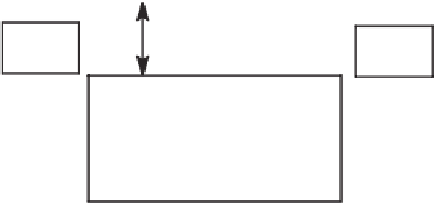
40 cm
LISN
LISN
EUT
1 x 1.5 METER TABLE
3.6 m x 4.9 m SHIELDED ENCLOSURE
QUASI-PEAK
ADAPTER
CONTROLLER
SPECTRUM
ANALYZER
Figure 4.15
Setup for performing conducted emissions testing in a shielded room. Measurements are taken using a line impedance stabi-
lization network (LISN). A spectrum analyzer and a quasi-peak adapter with a measurement bandwidth of 9 kHz are typically used to record
the conducted emissions.
Modify the
gure it as shown in the schematic diagram. You may
remove all except one of the power outlets to accommodate the components. The power
outlet used to connect to the device under test (J2) would be one of the power strip's orig-
inal power outlets.
Emissions radiated from this LISN are coupled inductively to a spectrum analyzer. L3
is a single loop of No. 14 stranded insulated wire that exits and reenters the power strip's
enclosure. The H-
fi
filter circuitry and con
fi
eld probe made of a VCR head, described above, would then be used
to pick up conducted emissions. Although this LISN does not yield results identical to
those of the standards, it makes it easy to detect emissions conducted by the device under
test into the power line. In addition, although conducted emissions tests should be per-
formed on both phases (hot and neutral) of the power line, most of
fi
ensive units reveal
themselves with just the hot-to-ground measurement provided by this LISN.
When the device is prepared for testing, the power cord in excess of the distance is
folded back and forth, forming a bundle 30 to 40 cm long in the approximate center of the
cable. Power supply cords for any peripheral equipment should be powered from an aux-
iliary LISN. Excess interface cable lengths should be bundled separately in a noninduc-
tive arrangement at the approximate center of the cable with the bundle 30 to 40 cm in
length. The emissions conducted are maximized by varying the operating states and
con
ff
guration of the device under test. The limits for conducted emissions per EN-55011
for group 1 devices are shown in Table 4.4. As an example, Table 4.5 shows the results
we obtained recently when testing an implantable-device programmer for conducted
emissions.
fi


Search WWH ::

Custom Search