Biomedical Engineering Reference
In-Depth Information
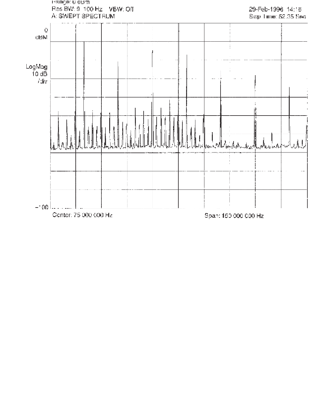
Figure 4.14
The spectral pattern obtained from the output of the comb generator can be used as a frequency ruler because it presents strong
spectral lines at every harmonic of the fundamental square wave. Notice the similarity between the envelope formed by the spectral compo-
nents of this 20-MHz comb and the nomograms of Figure 4.2.
Each of the 50-
µ
H inductors and 1-
µ
F capacitors form an unbalanced
fi
filter. The induc-
tors must be of su
ciently large wire gauge to carry the full ac current demanded by the
device under test with less than a 2-V drop. Conducted emissions are then measured using
a spectrum analyzer with quasi-peak detection. Measurements are taken between hot to
ground and then between neutral to ground. A 50-
Ω
resistor needs to be connected across
the 1-k
input. Switch
SW1 accomplishes phase selection and automatic shunting of the LISN leg not being
observed.
Note that the LISN established by the standards presents a 1-
Ω
resistor, which is not connected to the spectrum analyzer's 50-
Ω
F capacitance between
the hot line and the LISN and device under the test's safety ground. A ground fault could
lead to potentially lethal currents to operators in contact with the LISN or the device under
test. For this reason, it is advisable to wire the LISN's ground terminal permanently to
ground.
A safer way of running design-time tests is to use a LISN made from a modi
µ
fi
ed power
protector designed to
filter power line glitches prior to supplying power to computers and
other electronic equipment. The circuit for this LISN is shown in Figure 4.17. The input
connector and power cord, circuit breaker F1, and neon light are found almost universally
in power protector strips. You may also leave any MOVs that you
fi
fi
find in the power strip.

Search WWH ::

Custom Search