Graphics Reference
In-Depth Information
Frames
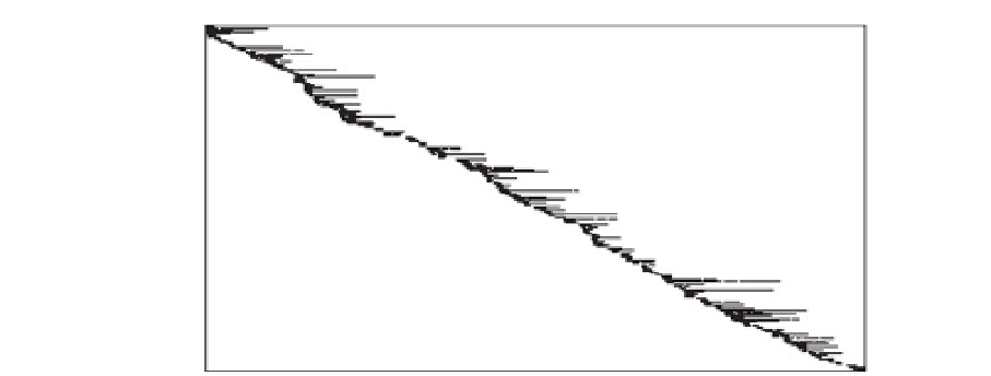
Figure 6.16.
A random sample of 200 of the 19,780 features tracked over a 383-frame sequence.
A dark box appears in the
(
th
position if feature
i
was detected in frame
j
. We can see that
features have various lifetimes and constantly enter and leave the field of view of the moving
camera.
i
,
j
)
(a)
(b)
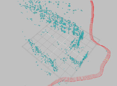
Figure 6.17.
The camera tracking result obtained for the video sequence. (a) Top view, illus-
trating the camera track and rough geometry of the building. The ground plane was manually
inserted based on the recovered scene points. (b) Side view, including the image and viewpoint
for a selected camera.
The quality of camera tracking can also be verified by adding
test objects
into the
reconstructed 3D coordinate system. For example, Figure
6.18
illustrates the same
frames as Figure
6.15
, with added synthetic geometric solids aligned to surfaces in the
to a real video sequence using matchmoving. In a visual effects company, a match-
move expert will typically fit a large number of planar surfaces to the scene to aid 3D
animators and compositors further down the pipeline.
23
Note that sometimes the objects “show through” physical surfaces in the scene in this simple
picture. The added synthetic objects are simply rendered on top of the original images using the
estimated camera perspectives. There is also no attempt to match the lighting of the scene, which
is essential for realism.