Environmental Engineering Reference
In-Depth Information
breakdown voltage of 11.0 V (12
1V)isselected. This ensures that the
capacitor is charged to at least 12 V before it discharges to the regulator.
However, a high breakdown voltage also implies that if the transducer is
compressed too lightly and the maximum voltage of the capacitor fails to
reach 12 V, no power will be supplied to the transmitter. R1, R2, and R3
should be as large as possible so that minimum current flows through them,
and resistive losses are minimized. As mentioned,
R
2
−
/
(
R
1
+
R
2)
>
V
GS
/
V
reg
,
and with
V
reg
at 5.0 V,
R
1=10M
.
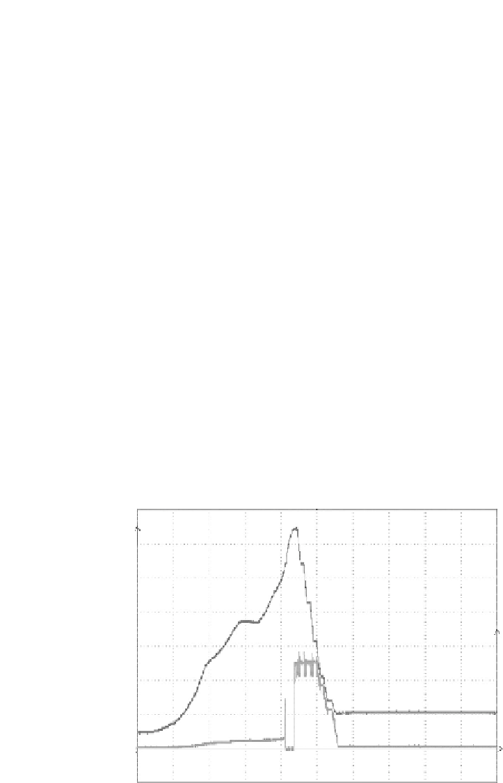
Experimental results shown in
Figure 4.24
illustrate the outcome of the
designed power management circuit. The voltage waveforms in
Figure 4.24
are measured across the storage capacitor and the voltage regulator of the
power management circuit. During one depression cycle: (1) As the human's
finger presses down onto the material, the harvested energy is stored in the
capacitor and not released to the load as the source and load are discon-
nected. The capacitor's voltage rises to around 7 V. (2) As the human's finger
stops pressing, energy is harvested again and stored in the capacitor. The
capacitor's voltage continues to rise to 13 V, which is more than the pre-
set voltage level, and energy is released to the load. Once the source and
load are connected, energy is supplied to the load, as can be seen in
Figure
4.24
where the output voltage of the load has been regulated by the voltage
regulator.
The circuit design of the receiver unit is shown in
Figure 4.25
. The design
basically is comprised of an RF receiver circuit, a timer, and a JK flip-flop. The
JK flip-flop is used to implement the simplest toggle design by connecting
its inputs together. A 555 timer is used as a timing device. The decoder has
a signal VT, which only turns high for a short duration when a signal from
,
R
2=5M
, and
R
3=10M
Main : 10 k
12
10
Storage Capacitor,
V
cap
8
6
6
4
4
2
2
Regulator,
V
reg
0
0
0.1
0.2
Max (C1)
Max (C2)
0.3
0.4
0.5
0.6
0.7
0.8
0.9
13.0000 V
5.66667 V
Min(C1)
Min(C2)
833.333 mV
-83.3333 mV
Time/ sec
FIGURE 4.24
Voltage waveforms across a storage capacitor and voltage regulator.


Search WWH ::

Custom Search