Graphics Programs Reference
In-Depth Information
In the properties window - “Scene” button,
ensure that “Gravity” is checked in the “Gravi-
ty” tab. Set up a scene as shown in Figure 14.24
by scaling the default cube object and then du-
plicating and transposing the duplication (see
Chapter 3 for a refresher). By duplicating the
cube you will have one cube named “Cube”
and another named “Cube.001.”
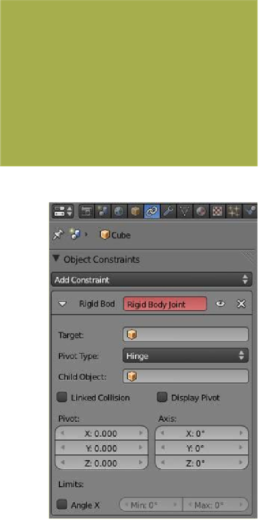
Select “Cube” in the 3D window, then in
the properties window - “Object Constraints”
button click on “Add Constraint” and select
“Rigid Body Joint.” Note that the constraint
type is highlighted in red, indicating that al-
though a constraint has been added, it is not
active (Figure 14.25). To activate the con-
straint, click in the “Target” selection bar and
select “Cube.001”—this links the owner of the constraint
to a fixed object in the scene (i.e., “Cube.001”). The con-
straint panel that displays will have “Pivot Type: Ball” se-
lected, so change this to “Hinge.” Check “Display Pivot” to
display the hinge pivot axes in the 3D window. To see the
axes more clearly, rotate the screen, turn off the manipula-
tion widget, change to wireframe viewport shading, and
zoom in on the window (Figure 14.26). You should now
see
px
,
py
, and
pz
hinge pivot axes displayed as broken
orange lines; the length of the lines are proportional to the
sides of the cube sides.
The object will only pivot about the
px
-axis when us-
ing the “Hinge” type constraint. We want “Cube” to pivot
Figure 14.24
Figure 14.25
Select “Cube.001”
in the drop down
menu.
Tick “Display Pivot.”
Hinge pivot axes
Figure 14.26