Graphics Programs Reference
In-Depth Information
Figure 14.21
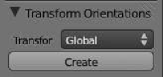
Figure 14.22
Change to “Local.”
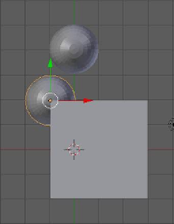
Figure 14.23
sphere's local axes. To do this, with the sphere selected, press the N key with the mouse cur-
sor in the 3D window to display the numeric panel. In the “Transformation Orientation” tab,
click on the “Transform” selection drop down menu and select “Local” (Figure 14.22). Rotate
the sphere until the
x
-axis points at the cube (Figure 14.23). As soon as the axis projects to a
surface on the cube, the sphere is located on the surface. By slowly rotating the sphere you will
see it move along the surface as the direction of the axis changes. In the “Object Constraints”
panel, the “Distance” and “Influence” sliders affect how far the sphere is located between its
original position and the surface of the cube. By checking “Axis X” and “Axis Y,” the projec-
tion line is at 45 degrees between the axes.
14.5.3 The Rigid Body Joint Constraint
The rigid body joint is used to constrain the movement of objects in the Blender game engine
(see Chapter 19 for more on the game engine). It is not intended to be used for the manipu-
lation of objects in the 3D window or in an animation. To provide an insight into the use of
this constraint, we will demonstrate a simple hinge constraint. In the game engine, a hinged
object such as a door would require a force to open and close it. To make our demonstration
as simple as possible, we will hinge a trapdoor and use the default gravity force in Blender.