Graphics Programs Reference
In-Depth Information
Figure 14.18
Figure 14.19
Figure 14.20
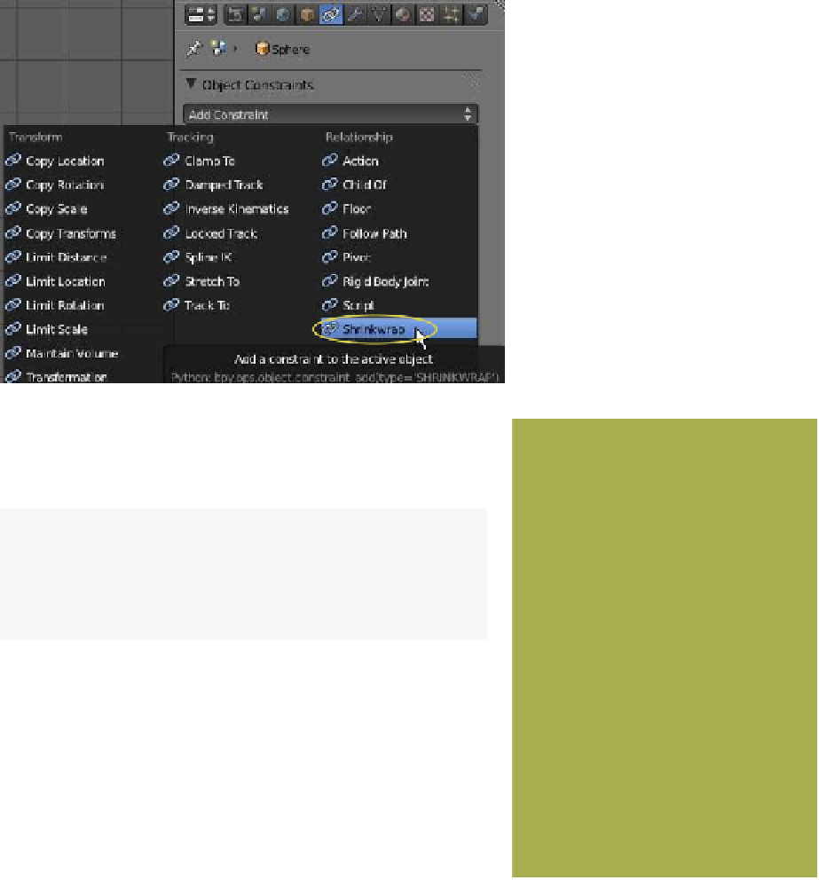
tab, click in the “Target” selection bar and select “Cube” as the tar-
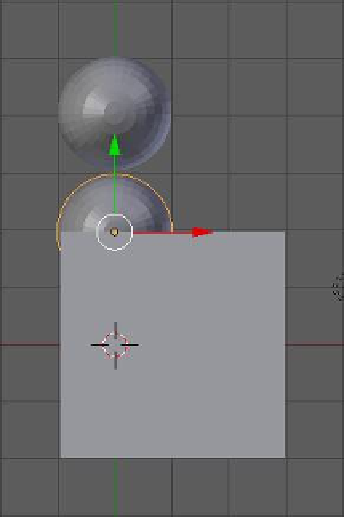
get (Figure 14.19). The sphere relocates, positioning its center on
the surface of the cube (Figure 14.20).
Original location
of the sphere
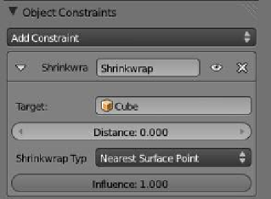
Note:
In the “Object Constraints” tab, the “Shrinkwrap
Type” is “Nearest Surface Point.” The sphere has therefore
located at the nearest point on the surface of the cube (the
target).
Relocated
sphere
In the “Object Constraints” tab, change the “Shrinkwrap
Type” to “Nearest Vertex” (Figure 14.21). With this option, the
sphere relocates to the nearest vertex on the target object. If the
“Shrinkwrap Type: Project” option is selected, the sphere will re-
vert to its original location (“Project”' means to project an axis
to the surface). In our setup, the sphere's axes are represented by
the red, green, and blue arrows of the transformation widget. By
default, the axes are the global axes of the imaginary 3D world
and with the sphere located in its original position you see that
neither of these axes are directed towards a surface on the cube.
Note that the direction of the widget arrows represent the
positive direction. With “Shrinkwrap Type: Project” selected, “Axis X,” “Axis Y,” and “Axis
Z” buttons are present in the properties window - “Object Constraints” tab. Check the
“Axis X” button. In order to project an axis towards a surface of the cube, we must rotate the