Hardware Reference
In-Depth Information
When sliding the rod up the tube it is a bit hard to spot the tapped hole through the clearance
hole. So I painted around the tapped hole with white paint so that it could be easily seen
through the clearance hole and lined up correctly.
Electronics
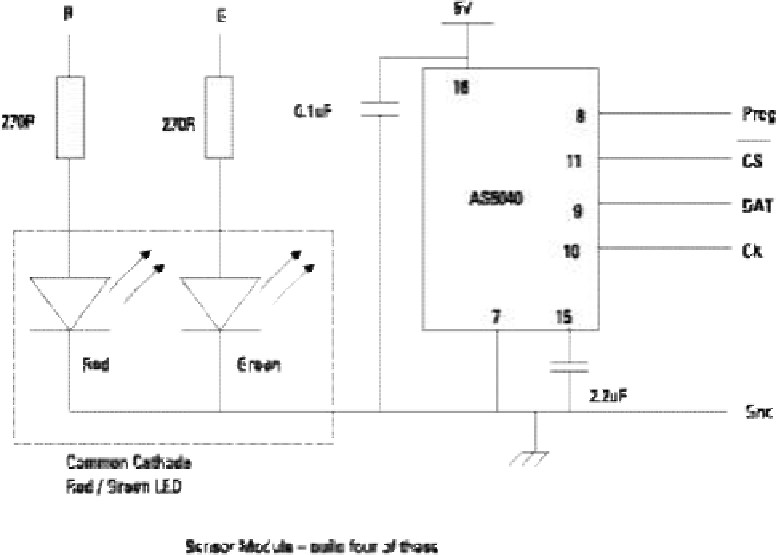
Next, you come to the electronics, which fortunately are not too complex - just the sensor
chip, some decoupling capacitors, two resistors and an LED. he AS5040 rotation sensor can
be used from either a 3V3 or 5V supply; I used the 5V supply because that gave the correct
voltage level of logic signals for the Arduino I used. A schematic of the sensing board is
shown in Figure 16-11. You need to build four of these. he capacitors should be of the
ceramic type and mounted as close to the chip as possible. he LED is a red/green common
cathode, which will allow you to have three colours: red, green and orange. hese are used to
indicate if the pendulum is being used to gather data and what axis it is controlling.
Figure 16-11:
A schematic of
one sensor
board.