Hardware Reference
In-Depth Information
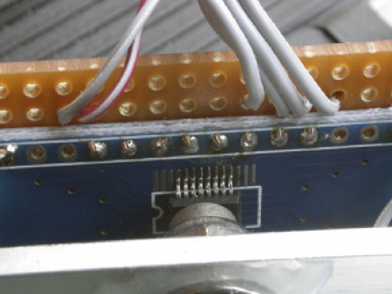
he only diiculty with this circuit is that the AS5040 is in a 16 pin SSOP package, with a
0.65 mm lead pitch. his is impossible to solder directly onto strip board, but fortunately
adaptor boards are available quite cheaply. I used a board designed for an SSOP28 chip, and
it converts the ine pitch to normal 0.1" pitch used on strip board. (Its full name is an SSOP28
to DIP28 0.65 mm pitch adapter transfer board, and I got it from Hong Kong through eBay.)
It covers more chip leads than you need, so just solder it in the centre with three blank con-
nections on each side. his then should be attached to some strip board by soldering solid
copper wires through the holes you want connections to. Make sure that the adaptor board
is as close as possible to the strip board. hen mount the strip board on the side of each alu-
minum channel so that the magnet is exactly over the centre of the chip. Separate the pillars
by an odd number of strips on the strip board so that the pillar mounting holes are equally
spaced from the centre of the bearing/magnet position. To get the distance between the
magnet and sensor correct, I used a 10 mm M3 tapped pillar, a nut and two M3 washers and
got the spacing between the magnet and chip to be 1 mm. Fortunately there is an electronic
way of telling if the magnetic strength is in the correct range; you will see about this later in
the chapter when you look at the data that comes from this sensor. he physical arrange-
ment is shown in Figures 16-12 and 16-13.
Figure 16-12:
he mounted
sensor board
showing the
chip.