Hardware Reference
In-Depth Information
up the threaded rod and applied epoxy to secure the second bearing (the one not carrying the
magnet) in place. In this way I got an exact it, and the threaded rods would turn on the bear-
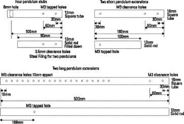
ings without any noticeable stif spots. he pendulum itself is a 12 mm square steel tube, 4"
long from the centre of the hole. he area of the tube above the hole needs to be rounded of
with a ile to prevent it from catching on the top of the aluminum channel. here are two holes
at the end of the tube; these should be drilled and tapped with an M3 thread. Although there is
not much to thread as the walls of the tube are so thin, this is compensated for by the material
being steel; still, overtightening might cause the thread to strip.
I gave two of the four pendulums, numbers 2 and 4, a solid core of steel by iling down two
edges of some 12 mm square steel rod so that it slides inside the tube. hen I marked the posi-
tion of the tapped holes on the solid rod, drilled out 3.5 mm clearance holes and inally applied
some epoxy to hold them in place. You could do that with the other two pendulums as well, but
there is little point as these are going to eventually be much longer. he idea is that the basic
length of the pendulum is the third harmonic; then there are two sizes of extension rod you can
use to get the second harmonic and the fundamental. hese are shown in Figure 16-10. he
short extensions have a solid square completely contained in the tube, whereas the long exten-
sion has the solid rod protruding from the end and the choice of a number of holes along the
square tube to attach it, giving you some variability on the length of this largest pendulum. Use
positions 1 and 3 for the long pendulum extensions and positions 2 and 4 for the short ones.
Figure 16-10:
he pendulum
sections.