Hardware Reference
In-Depth Information
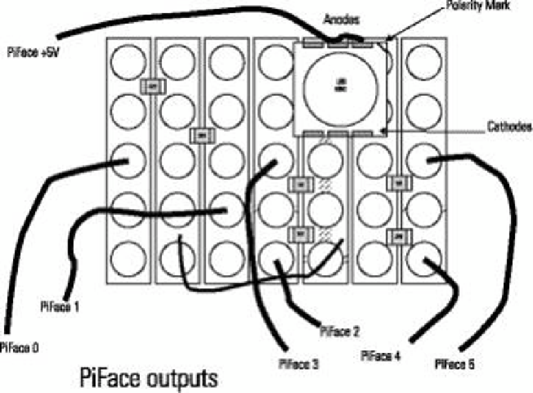
Next you need add the components. Figure 8-7 shows how they are arranged. You need a ine
pair of tweezers and a magnifying glass. Take the 5050 LED and make sure that the polarity
mark is at the top. It marks the three anodes; if you are not sure, use the multimeter test tech-
nique described earlier. he critical point is to line things up so that the left-most two anode
connections connect to diferent strips of the half strip you have cut out. Now remove the LED
and just put the smallest dab of solder on the strip board where the left cathode connection is
going to be. Now with your iron in one hand and the tweezers with the LED in the other, align
the LED again and touch the iron on the solder. Position the LED lat on the board and then
remove the iron. Keep the LED still while the solder sets. Now check that it is aligned correctly.
If not, reapply the iron and straighten it with the tweezers. Only when you are sure that it is
positioned correctly apply solder to the other connections. he anodes should be joined
together by applying suicient solder so that the two tracks are bridged.
Figure 8-7:
Circuit layout
using surface
mount
components.
Now you need to add the resistors. You could use through hole at this point, but you might
as well go for surface mount. A surface mount resistor should sit nicely between the tracks of
0.1˝ pitch strips. Note how surface mount resistors are labeled. hey use three numbers: he
irst two are actual numbers, and the third one says how many zeros there are. So a resistor
marked “471” is 470 ohms. here are two sizes that will do this: he larger is known as
0806,
and the smaller as
0604;
either size will do. (I used the smaller resistor size.) A photograph of