Biomedical Engineering Reference
In-Depth Information
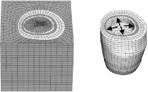
Figure 12.12:
Left - FE mesh for forward model used to create target image.
Right - A detailed view of the mesh corresponding to myocardial wall. Black
arrows indicate the pressure load applied to the endocardial surface.
NIKE3-D finite element program [92] (Fig. 12.12). Using the deformation map
obtained from the forward FE analysis, a deformed volumetric image dataset
(target) was created by applying the deformation map to the original template
MRI image (Fig. 12.12, right panel).
A Warping model was created using the same geometry and material parame-
ters that were used in the forward model described above. The Warping analysis
was performed using the template image data set and a target image dataset
was created by applying the forward model's deformation map to deform the
template image. This yielded a template and target with a known solution for the
deformations between them. The forward FE and Warping predictions of fiber
stretch (final length/initial length along the local fiber direction) were compared
to determine the accuracy of the technique. The validation results indicated
good agreement between the forward and the warping fiber stretch distribu-
tions (Fig. 12.13). A detailed analysis of the forward and predicted (Warping)
stretch distributions for each image plane indicated good agreement (Fig. 12.14).
To determine the sensitivity of the Warping analysis to changes in material
parameters,
µ
and
C
3
were increased and decreased by 24% of the baseline
values. The 24% increase and decrease corresponds to the 95% confidence inter-
val of material parameters determined from the least-squares fit of the material
model to the Humphrey et al. data [31, 32]. Since, the proper material model
is often not known for biological tissue, the material model was changed from
the transversely isotropic model described above to an isotropic neo-Hookean