Graphics Programs Reference
In-Depth Information
Displaying Profiles in Profile views
In the AutoCAD
®
Civil 3D
®
software, you must use a
profile view
to display a
profile. A profile view is basically a grid that represents stations in the
x
direction
and elevations in the
y
direction. The stations along the alignment and their cor-
responding elevations are plotted on this grid, and the resulting line represents
changes in the terrain along the alignment. The profile view also includes various
types of labels, such as axis labels and axis titles, to provide context to the display
of the profile. Profile views can be further augmented with bands, which will be
covered in Chapter 8, “Displaying and Annotating Profiles.”
Certification
Objective
Exercise 7.2: Create a Profile view
In this exercise, you'll create a profile view to display the surface profile that you
created in the previous exercise.
If you haven't already done so, go to the topic's web page at
www.sybex.com/
go/civil3d2015essentials
and download the files for Chapter 7. Unzip the files
to the correct location on your hard drive according to the instructions in the
introduction. Then, follow these steps:
There are tons of set-
tings here, but for
now you'll accept the
defaults and skip
right to creating the
profile view.
1.
Open the drawing named
Profile View.dwg
located in the
Chapter 07
class data folder.
2.
Click the Jordan Court alignment, and then click Profile View on the
contextual ribbon tab.
◀
3.
In the Create Profile View - General dialog box, click Create Profile View.
4.
When prompted for the profile view origin, click a point in the open
area to the east of the project.
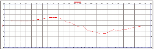
A new profile view is inserted into the drawing, as shown in
Figure 7.1.
◀
The profile view origin
is the lower-left corner
of the profile view.
5.
Save and close the drawing.
FiGuRE 7.1
The newly created profile view