Graphics Programs Reference
In-Depth Information
5.
Click the Calculate button at the bottom to test the strength of the
belt. The belt should pass with no issues.
6.
Click OK to close the dialog.
If the belt's elements aren't properly located, you can't run the calculation.
This is a great tool that can help you design with confi dence.
Now, let's move on to learn the full effects of adding the belt to your assembly.
Locating the Motor
Now that you've set a length for the belt, let's locate the motor to it:
1.
Start the Constrain tool.
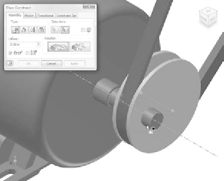
2.
Place a mate between the axis of Pulley1 and the shaft of the motor.
See Figure 7.18.
FIGURE 7.18
Locating the motor to the pulley
3.
Click OK to create the constraint.
4.
Restore the Envelope Suppressed LOD.
5.
Save your work, which should now look like Figure 7.19.
Now that you've added the critical elements to the function of your assembly,
you can go back and make some changes for clearance as well as reduce the
strain on some of the power train.


Search WWH ::

Custom Search