Graphics Programs Reference
In-Depth Information
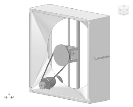
FIGURE 7.19
Bearings, shaft, and belts added to the assembly
Modifying Pulley2
Let's start out by reducing the mass of Pulley2. When the V-Belts tool places the
pulleys, the assumption is that you'll want to modify them in the way that you
traditionally build these components; so, Inventor creates blanks. With that,
let's lighten the load:
1.
Set your selection fi lter to Select Part Priority.
2.
Pick Pulley2, right-click, and select Open to bring up Pulley2 in a
new window.
3.
Use the ViewCube to orient the part so that you're looking at the
front view and the word
Front
is legible.
4.
Start a new sketch of the face closest to you.
5.
Draw two circles concentric to the sketch center.
6.
Set their diameters to
7.8
and
1.3
, as shown in Figure 7.20.
7.
Start the Extrude tool.
8.
Set the function to cut and select the ring between the two sketched
circles. Set Extents to All, and make sure the cut is going through
the part as shown in Figure 7.21.


Search WWH ::

Custom Search