Graphics Programs Reference
In-Depth Information
13.
You can choose a special name for the template in the Template
Description dialog. In this case, keep the default and click OK to cre-
ate the new template.
Doing so adds the new template to the list.
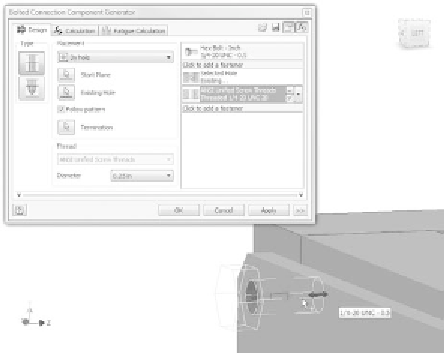
FIGURE 5.27
Dragging the length of a bolt changes the standard length.
14.
Click OK to start generating the bolted connections.
15.
When the File Naming dialog appears, deselect the Always Prompt for
Filename check box, and click OK.
This generates the four bolts (Figure 5.28) and, in most cases, four threaded
holes in the parts they go through. In this case, due to the nature of the fan
support assembly — a frame with many members — the holes appear only
under the part beneath the fi rst hole of the pattern.
A simple remedy would be to project the bearing support hole locations onto the
unedited parts and add the threaded holes similar to the way you added holes to
the frame in Chapter 2, “Building the Foundation of the Design.” For the purpose
of moving forward, you'll leave the fan support assembly short a few holes. I
wanted to use this as an example of an unusual condition where a design accel-
erator might not be able to understand all of the design intent.


Search WWH ::

Custom Search