Graphics Programs Reference
In-Depth Information
Constrain Sketch Plane to Selected Face or Plane
After you finish
filling out the dialog and select OK to create a component, Inventor
asks you to select a plane to align the new component to. With this
option selected, Inventor also creates a constraint between the
selected plane or face in the assembly and the new sketch.
3.
Set the values in the dialog to create a new component named
frame envelope based on the
Standard (in).ipt
template in the
C:\Data\Parts
folder and using the Constrain Sketch Plane to
Selected Face or Plane option.
4.
Click OK to begin creating the new component in the assembly.
5.
Inventor needs you to select a face or plane. Expand the assembly's
Origin
folder, and select the YZ plane to base the new part on.
This creates the new component and starts a new sketch oriented
on the plane you selected.
6.
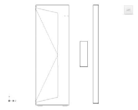
Add two rectangles to the sketch, as shown in Figure 5.2.
FIGURE 5.2
Beginning the new sketch
7.
Use the Coincident constraint to link the midpoint of the left vertical
line on the large rectangle to the midpoint of the right vertical line
on the small rectangle.


Search WWH ::

Custom Search