Graphics Programs Reference
In-Depth Information
In the Automated Centerlines dialog are options for the type of geom-
etry on which you want to place centerlines in the Apply To group. In
the Projection group, you can limit whether the centerlines are applied
to objects in the view with the axis normal, axis parallel, or both.
12.
Set Apply To for Hole features only, and set the Projection to axis nor-
mal and axis parallel.
13.
Click OK to create the centerlines as shown in Figure 4.47.
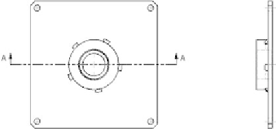
FIGURE 4.47
You can place center marks and centerlines in several views
simultaneously.
Now you'll create a manually placed centerline.
Creating a Centerline Bisector
Sometimes you need to display a centerline but don't have circles or arcs to use
as a basis for the Centerline tool. You'll also often want to show a centerline
down the middle of parts or features such as shafts, conical parts, slots, or the
side view of a hole.
In the section view, you can see the inside of the hole. The Centerline tool
allows you to fi nd the center of the hole even from the side, but the Centerline
Bisector tool does this and lets you bisect nonparallel edges as well. When you
select the tool, it prompts you to click a location like the other center mark tools
do; but in this case, it's looking for line segments, not arcs or circles:
1.
Start the Centerline Bisector tool from the Symbols panel.
2.
In the section view, pick both sides of the elevated cylinder. See
Figure 4.48.
3.
End the Centerline Bisector tool.


Search WWH ::

Custom Search