Graphics Programs Reference
In-Depth Information
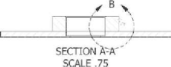
FIGURE 4.48
Select the two edges for placing the centerline.
4.
In the section view, click and drag the View callout down to give the
new centerline more room.
5.
Click and drag the endpoints of the centerline until you can clearly
see the linetype. See Figure 4.49.
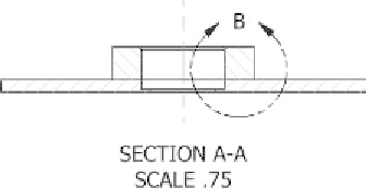
FIGURE 4.49
Pick and drag to edit the length of centerlines.
You'll have a chance to use the Centerline tool later in the chapter. For now,
let's add some dimensions to the drawing.
Placing Dimensions in Inventor
Simple tools like the Center Mark tools are necessary to create drawings cor-
rectly. You'll learn other drawing tools in later chapters, but for now let's exam-
ine the ever-important dimensioning tools.
Your approach to dimensioning will vary with the national and corporate
standards that you must adhere to. The dimensioning tools in Inventor follow
the standards that you select for their appearance, but the basic tools are the
same regardless of what that standard is. In this chapter, we'll discuss the
General Dimension, Baseline Dimension, Hole/Thread Notes, Retrieve
Dimension, and various dimension-editing tools.


Search WWH ::

Custom Search