Graphics Programs Reference
In-Depth Information
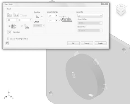
5.
Set the Bead height to
.13
. Set the Intermittency length to
.25
and
the spacing to
1.4
, as shown in Figure 4.20.
FIGURE 4.20
Applying a chain weld around the bearing holder
6.
Pick the Machining icon from the Process panel. As with the welds,
this activates a specifi c set of modeling tools.
7.
Start the Hole tool from the Preparation and Machining panel.
8.
Set Placement to Concentric.
9.
Pick the top face of the bearing holder for the plane and the circular
edge for the concentric reference.
10.
Switch the type to Counterbore. Set the diameter to
1.27
, the depth
to
.65
, and the drill diameter to
1
. Set Termination to Through All, as
shown in Figure 4.21.
11.
Pick the OK button to create the bore.
12.
Pick the Chamfer tool from the Preparation and Machining panel.
13.
Add a chamfer to the top inside edge of the new bore, as shown in
Figure 4.22. Make the Distance value of the chamfer 1mm. Inventor
does the calculation for you; but what's more important is that if
you edit the chamfer later, it will remember that the original value
was 1mm.


Search WWH ::

Custom Search