Graphics Programs Reference
In-Depth Information
8.
Click OK to begin placing the component.
9.
Place the screw somewhere where you can see it in the Design window.
10.
Start the Constrain tool.
11.
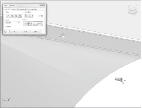
Select the Insert Type, and use the Aligned Solution for the constraint.
12.
Select the top edge of the countersunk hole and the top edge of the
screw, as shown in Figure 3.40. (I have turned off the preview for the
screen capture. You should leave the preview on.)
FIGURE 3.40
The Insert constraint only uses curved edges for placement.
13.
Click the OK button to place the screw.


Search WWH ::

Custom Search