Hardware Reference
In-Depth Information
D
0
D
1
D
2
A
A
D
3
A
B
B
D
4
B
D
5
C
C
C
D
6
D
7
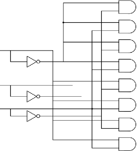
Figure 3-13.
A three-to-eight decoder circuit.
The operation of the circuit of Fig. 3-13 i
s
straightforward. Each
AN
D
gate has
three inputs, of whic
h
the first is either
A
or
A
, the second is either
B
or
B
, and the
third is
e
i
t
h
er
C
or
C
.
E
ach gate is enabled by a different combination of inputs:
D
0
by
A B C
,
D
1
by
A BC
, and so on.
Comparators
Another useful circuit is the
comparator
, which compares two input words.
The simple comparator of Fig. 3-14 takes two inputs,
A
and
B
, each of length 4
bits, and producesa1iftheyareequal and a 0 otherwise. The circuit is based on
the
XOR
(EXCLUSIVE OR) gate, which puts outa0ifitsinputs are equal and a 1
otherwise. If the two input words are equal, all four of the
XOR
gates must output
0. These four signals can then be ORed together; if the result is 0, the input words
are equal, otherwise not. In our example we have used a
NOR
gate as the final
stage to reverse the sense of the test: 1 means equal, 0 means unequal.