Hardware Reference
In-Depth Information
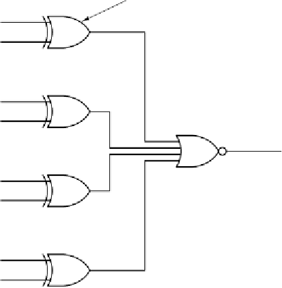
EXCLUSIVE OR gate
A
0
B
0
A
1
B
1
A=B
A
2
B
2
A
3
B
3
Figure 3-14.
A simple 4-bit comparator.
It is now time to move on from the general-purpose circuits discussed above to
combinational circuits. As a reminder, combinational circuits have outs that are
functions of their inputs, but circuits used for doing arithmetic do not have this
property. We will begin with a simple 8-bit shifter, then look at how adders are
constructed, and finally examine arithmetic logic units, which play a central role in
any computer.
Shifters
Our first arithmetic circuit is an eight-input, eight-output shifter (see
Fig. 3-15). Eight bits of input are presented on lines
D
0
,...,
D
7
. The output,
which is just the input shifted 1 bit, is available on lines
S
0
,...,
S
7
. The control
line,
C
, determines the direction of the shift, 0 for left and 1 for right. On a left
shift,a0isinserted into bit 7. Similarly, on a right shift,a1isinserted into bit 0.
To see how the circuit works, notice the pairs of
AND
gates for all the bits ex-
cept the gates on the end. When
C
1, the right member of each pair is turned on,
passing the corresponding input bit to output. Because the right
AND
gate is wired
to the input of the
OR
gate to its right, a right shift is performed. When
C
=
=
0, it is
the left member of the
AND
gate pair that turns on, doing a left shift.