Hardware Reference
In-Depth Information
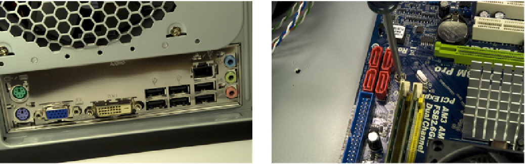
Figure 8-33.
Verify that none of the grounding tabs on the I/O
shield have fouled motherboard I/O port connectors
Figure 8-34.
Drive screws through the motherboard mounting
holes and into their corresponding standoffs
You'll need to apply some pressure against the springiness of the I/O shield
to align the motherboard mounting holes with the standoffs. Get a second
mounting hole aligned with its standoff and install a second screw. Once
you've driven in the second screw, all of the mounting holes should align
properly with their corresponding standoffs. Tighten all six motherboard
mounting screws finger-tight, plus at most a quarter turn. Do not overtighten
them, which risks cracking the motherboard.
Remove the cable tie that secures the bundle of cables from the power sup-
ply. Locate the ATX12V power cable, and route it to the ATX12V socket on the
motherboard, located between the processor socket and the rear I/O panel.
The ATX12V socket and plug are keyed. Orient the plug properly with the sock-
et and press the connector into place, as shown in Figure 8-35.
Locate the 24-pin main ATX power cable in the power supply cable bundle,
and route it to the front edge of the motherboard, just in front of the memory
slots. The plug and jack are keyed. Orient the cable connector properly relative
to the motherboard socket and press the cable connector into place, as shown
in Figure 8-36. Make certain that the latch on the cable connector snaps into
place over the tab on the motherboard connector to lock the cable into place.
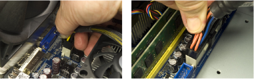
Figure 8-35.
Connect the ATX12V power cable from the power
supply to the motherboard
Figure 8-36.
Connect the 24-pin main ATX power cable from the
power supply to the motherboard