Hardware Reference
In-Depth Information
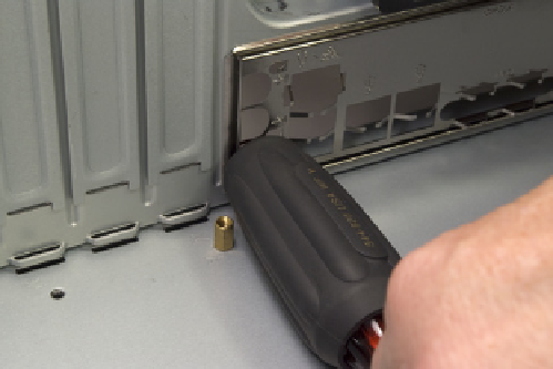
Figure 8-28.
Use a tool handle to press on the outside of the I/O
shield until it pops free
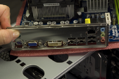
Figure 8-29.
Verify that the custom I/O shield supplied with the
motherboard in fact matches the rear I/O panel of the motherboard
Figure 8-30.
Position the I/O shield and press gently until it snaps
into position
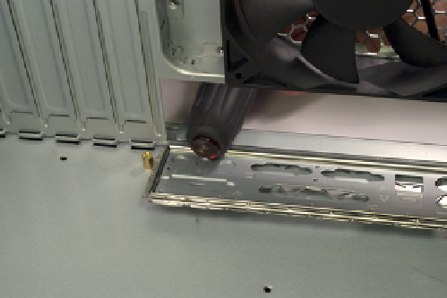
Figure 8-31.
Mark the chassis holes that need standoffs to be
installed
After you locate and mark the four additional mounting holes that require
standoffs, hold the motherboard directly over the case and look straight down
through each mounting hole in the motherboard to verify that you've marked
the correct holes. Then locate the four additional standoffs in the parts bag
and install them, as shown in Figure 8-32. You can use your fingers to install
and tighten the standoffs, but we found it easier to use our 5 mm nut driver.
Do not overtighten the standoffs, or you risk stripping the threads.
InstallingtheMotherboard
Slide the motherboard into position. Before you begin driving in screws to se-
cure the motherboard, examine the back panel carefully to make sure that
none of the grounding tabs on the I/O shield intrude into the motherboard
port connectors, as shown in Figure 8-33. A bright flashlight is helpful here.
When you're sure the motherboard is properly positioned relative to the I/O
shield, install one screw through the motherboard and into a standoff, as
shown in Figure 8-34. Tighten that screw only partially.
Figure 8-32.
Install four additional stand-
offs in the marked mounting holes