Hardware Reference
In-Depth Information
With the processor seated and clamped into place, the next step is to install
the CPU cooler. Before you install the cooler, examine the bottom of the heat-
sink to verify that the patch of thermal compound is present and undamaged.
When Recycling Is Bad
If you ever remove and replace the
processor, don't attempt to reuse
the thermal compound. Rub off any
compound present on the processor
surface and the heatsink base—if it's
tenacious, you can warm it slightly
with a hair dryer—and then polish
both the processor surface and the
heatsink base with a clean paper
towel to remove all traces of the
old compound. Apply new thermal
compound according to the instruc-
tions supplied with it. (We generally
use Antec Silver thermal compound,
which is inexpensive and effective.)
The CPU cooler mounts to the processor socket using two shiny metal latches
on the CPU cooler that fit over two black plastic tabs on the processor socket.
One of those latches is free-floating, and the other has a camming lever that
allows the CPU cooler to be locked into place. The CPU cooler can be oriented
so that either latch fits over either tab, but it's more convenient to use the
free-floating latch toward the interior of the motherboard (where there is less
clearance) and the cammed latch on the edge of the motherboard.
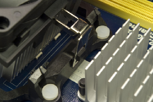
Examine the CPU cooler and locate the side with the free-floating latch. Tilt the
opposite side of the CPU cooler up slightly, and hook the free-floating metal
latch over the black plastic tab on the side of the processor socket near the
passive heatsink, as shown in Figure 8-20.
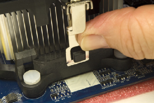
Pivot the CPU cooler down and into full contact with the processor, making
sure that the first latch remains connected. Maintaining finger pressure to
keep the CPU cooler in position, press the second (cammed) latch into posi-
tion over the second black plastic tab, as shown in Figure 8-21.
Figure 8-20.
Hook the free-floating metal latch over the black
plastic tab on the processor socket
Figure 8-21.
Press the cammed latch into position over the second
tab
Verify that both latches are secured over both tabs, and then press the black
plastic cam lever down until it latches to lock the CPU cooler to the processor
socket, as shown in Figure 8-22.
Ordinarily, the next step would be to connect the CPU cooler fan power cable
to the motherboard CPU fan header pins. In this case, though, the position of
the CPU fan header pins made it more convenient to install the memory be-
fore we connected the CPU fan.
With the processor installed, the next step is to install the memory modules.
To begin, swing open the DIMM locking tabs on both sides of both memory
sockets, as shown in Figure 8-23.