Hardware Reference
In-Depth Information
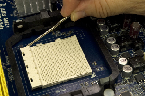
Figure 8-17.
Release the cam lever from the processor socket and lift it up
Open the outer box of the processor and remove the hard plastic shell that
contains the processor. Open that package carefully. Touch the chassis or pow-
er supply to ground yourself before you touch the processor itself. Remove the
processor from the antistatic foam bed on which it rests. Align and orient the
processor carefully with the processor socket. The socket and processor are
keyed, with an arrow on one corner of the processor and a corresponding key
on one corner of the processor socket.
When you have the processor and socket aligned, simply drop the processor
into the socket, as shown in Figure 8-18. The processor should seat fully with
no pressure whatsoever.
Do not apply any pressure
; doing so risks bending
the fragile contact pins. If the processor doesn't drop into the socket freely,
it's not aligned properly. Realign it and try again until it drops easily into the
socket and seats completely.
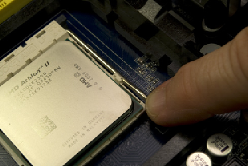
Once the processor is seated properly, swing down the metal cam lever and
snap it into place under the plastic locking tab on the socket, as shown in Fig-
ure 8-19. You should feel slight resistance on the cam lever as the cam clamps
the socket onto the processor pins. If the resistance is anything more than
slight, back up and start over.
Figure 8-18.
Orient and align the processor properly with the
socket and then drop it into place
Figure 8-19.
Press the cam lever down and snap it into place under
the plastic locking tab on the processor socket