Hardware Reference
In-Depth Information
Figure 7-6.
Verify that the I/O shield matches the motherboard
rear-panel ports
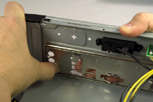
Figure 7-7.
Position the I/O shield and snap it into place
The I/O shield should snap into place, although getting it to seat properly
sometimes requires several attempts. As you apply pressure from inside the
case against the template, use your finger to apply offsetting pressure on the
outside of the template to avoid bending it. If you can't get it to snap into
place using finger pressure alone, use the handle of your screwdriver to press
along the edges until you feel it seat.
See the Light
If you simply look at the mother-
board, it's easy to miss one of the
mounting holes in all the clutter. We
generally hold the motherboard up
to a light, which makes the mounting
holes stand out distinctly.
Be careful not to bend the I/O shield when you seat it. The template holes need
to line up with the external port connectors on the motherboard I/O panel. If
the template is bent even slightly it may be difficult to seat the motherboard
properly. After you seat the I/O shield, temporarily place the motherboard
in position to verify that the back-panel I/O ports on the motherboard align
properly with the corresponding holes in the I/O shield.
Once you're sure the I/O shield is installed and aligned properly, hold the
motherboard over the case, aligned and positioned as it will be when it is in-
stalled in the case. Look down through each motherboard mounting hole to
locate the mounting positions on the base of the case. The goals are to make
sure that there is a standoff installed that corresponds to each motherboard
mounting hole, and that no extra standoffs are installed.
Check and Double Check
If your case comes with preinstalled
standoffs, make absolutely cer-
tain that each standoff matches a
motherboard mounting hole. If you
find one that doesn't, remove it.
Leaving an “extra” standoff in place
may cause a short circuit that could
damage the motherboard and/or
other components.
If necessary, install and/or remove standoffs until each motherboard mount-
ing hole has a standoff and each standoff has a motherboard mounting hole.
You'll probably be able to use your fingers to install or remove standoffs. If the
fit is too tight for finger pressure alone, use needlenose pliers.
Once you've installed and/or removed the standoffs required to match the
motherboard mounting hole configuration, do a final check to verify that (a)
each motherboard mounting hole has a corresponding standoff, and (b) no
standoffs are installed that don't correspond to a motherboard mounting hole.
The Intel D510MO motherboard has four mounting holes. The Antec ISK300-65,
like many cases, ships with several standoffs preinstalled. All four of the stand-
offs preinstalled in the ISK300-65 corresponded with mounting holes on the
D510MO motherboard, so we didn't need to install or remove any standoffs.
Place the prepared case aside for now.