Hardware Reference
In-Depth Information
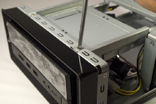
The next step is to remove the drive tray assembly. To do so, remove the three
Phillips screws—one at the center rear and one each at the left and right
front—that secure it to the chassis frame, as shown in Figure 7-4. Grip the
middle of the tray, as shown in Figure 7-5, and slide the tray toward the rear
of the chassis until it comes free. Lift the drive tray clear of the chassis and put
it aside.
Figure 7-4.
Remove the three Phillips screws that secure the drive
tray to the frame
Figure 7-5.
Slide the drive tray back and lift it off
With the drive tray removed, the inside of the case is visible. If you've spent
any time inside a PC before, the first thing you'll probably notice is that there
are lots of power supply wires, but no power supply. That circuit board at the
lower front of the case accepts 19VDC from the power brick and converts it to
the voltages needed by the system components.
You'll also notice a thin metal I/O shield, which you can put aside for later dis-
posal. Nearly every case we've used, including the Antec ISK300-65, includes a
generic I/O shield whose holes never seem to match the port arrangement on
any motherboard ever manufactured on planet Earth. We're not sure why case
manufacturers include these worthless bits of metal.
But we do need to install an I/O shield, both to block dust from entering the
large hole that would otherwise be present and to make sure the case pro-
vides proper ventilation to the processor and chipset. Open the motherboard
box and locate the I/O shield provided with the motherboard. Before you
proceed, place that I/O shield against the back panel of the motherboard, as
shown in Figure 7-6, to verify that the holes in the template match the ports on
the motherboard. (You might think the template and motherboard are guar-
anteed to match, since they came in the same box. Not always. We've found
mismatched I/O shields supplied with more than one motherboard, including
some from first-tier manufacturers.)
You Can't Get There from Here
If you're using the Antec ISK300-65
case and Intel D510MO mother-
board, jump forward and read the
section on seating and securing the
motherboard before you actually
install the I/O shield.
Once you've done that, install the custom I/O shield. Working from inside the
case, align the bottom, right, and left edges of the I/O shield with the match-
ing case cutout. When the I/O shield is positioned properly, begin on one
corner and press gently along the edges to seat it in the cutout, as shown in
Figure 7-7.