Hardware Reference
In-Depth Information
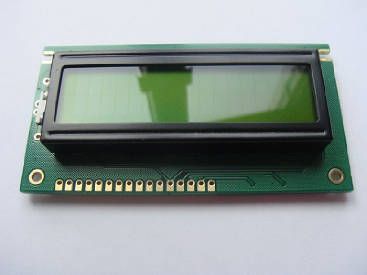
On my LCD, as you can see in Figure
4-2
, I have both pins 15 and 16 as well as anode and cathode solder pads on
the side solder pad for the backlight (you can see this on the left-hand side on the white pad). The pad configuration
on my LCD is one single row, which makes it quite easy to solder a pin header on.
Figure 4-2.
The front of a generic HD44780 display
If I flip the LCD over and take a look at the back of the printed circuit board (PCB), it appears that pins 15 and 16
may be connected to the anode and cathode of the LCD backlight. Now, you don't want to just guess it's connected, do
you? That's a perfect way to let the magic smoke out. This is where the ohm setting on your multimeter comes in real
handy. Remember that ohms are the measure of resistance. If you set your multimeter to the ohms setting and touch
the two probes together, what happens? You get a reading of zero. That means there is no resistance between each
probe. If you move the probes away, you will see the value rising back to a positive integer. This is called continuity
testing. With this in mind you can use continuity testing to measure the resistance between pins 15 and 16 and the
anode and cathode. Take a look at Figure
4-3
: you can see the pin out listing including pins 15 and 16. You will notice
that pins 15 and 16 have no label; I had to use my multimeter to figure out what they were connected to.